
2 layers28.3 × 14.3 mm
Tap Photosensor PCB
VoronDesign/Voron-Tap
Tap is a nozzle-based z-probe for the V2 and Trident printer designs. The entire toolhead moves to trigger an optical switch. Tap offers many advantages:
18 parts716GPL-3.0

 samanbeer/PD65W_Charger
https://forge.hackclub.com/projects/1660
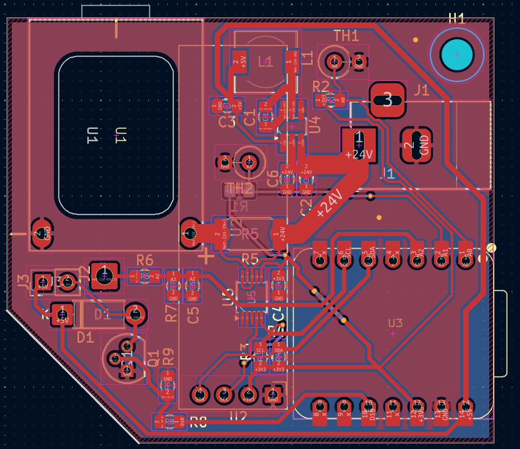
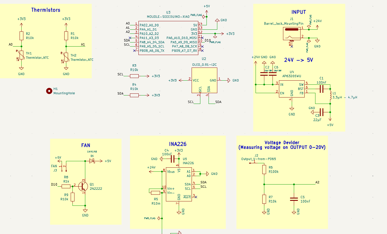
PD65W Charger is an open-source printed circuit board by samanbeer, from the samanbeer/PD65W_Charger repository on GitHub. It is a 2-layer board of 50.9 × 44.4 mm with 29 parts on 27 nets, routed with 194 tracks and 8 vias.
It is built around the AP63205WU and R10M. Its parts include 9 resistors, 6 capacitors, 5 ICs, 3 connectors and 1 diode. It belongs with the power boards of this library.


A few months ago, I bought a small PD65W module on AliExpress to charge my phone and laptop from old 20V laptop adapter. I designed a simple 3D printed enclosure for it (which I also shared on MakerWorld!).
But when I connected a 65W power bank, and it was running at max power, the module and adapter was extremely hot! I also taped 10kΩ thermistor on the top of the power source on surface and I measured with multimeter temperatures over 55°C (temperature from termistors is calculated from table based on resistance), and the internal heat was melting the PLA enclosure. And yes, I could just print it in PETG or ASA but that would not solve problem for this extreme heat.
That inspired me to build my own super smart charger that fixes issues of with my old charger, so i added:
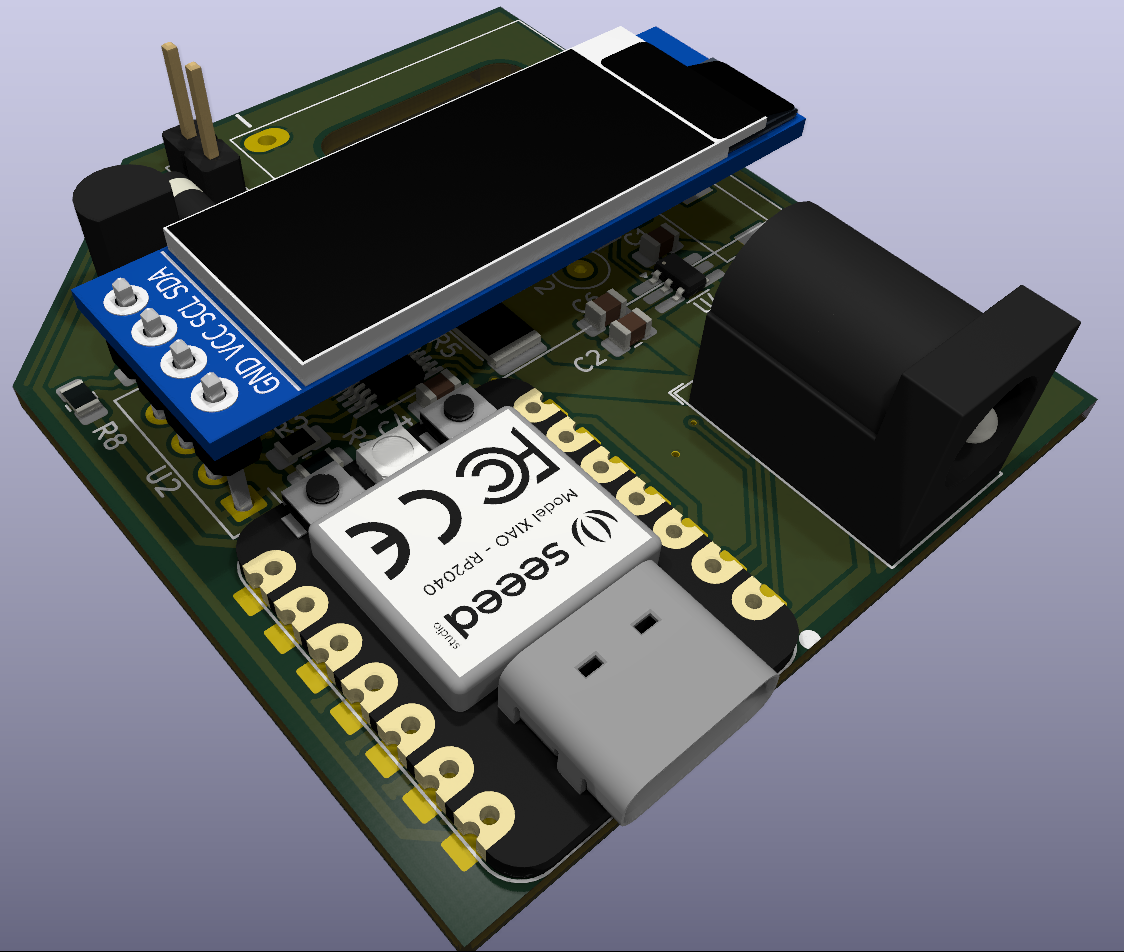
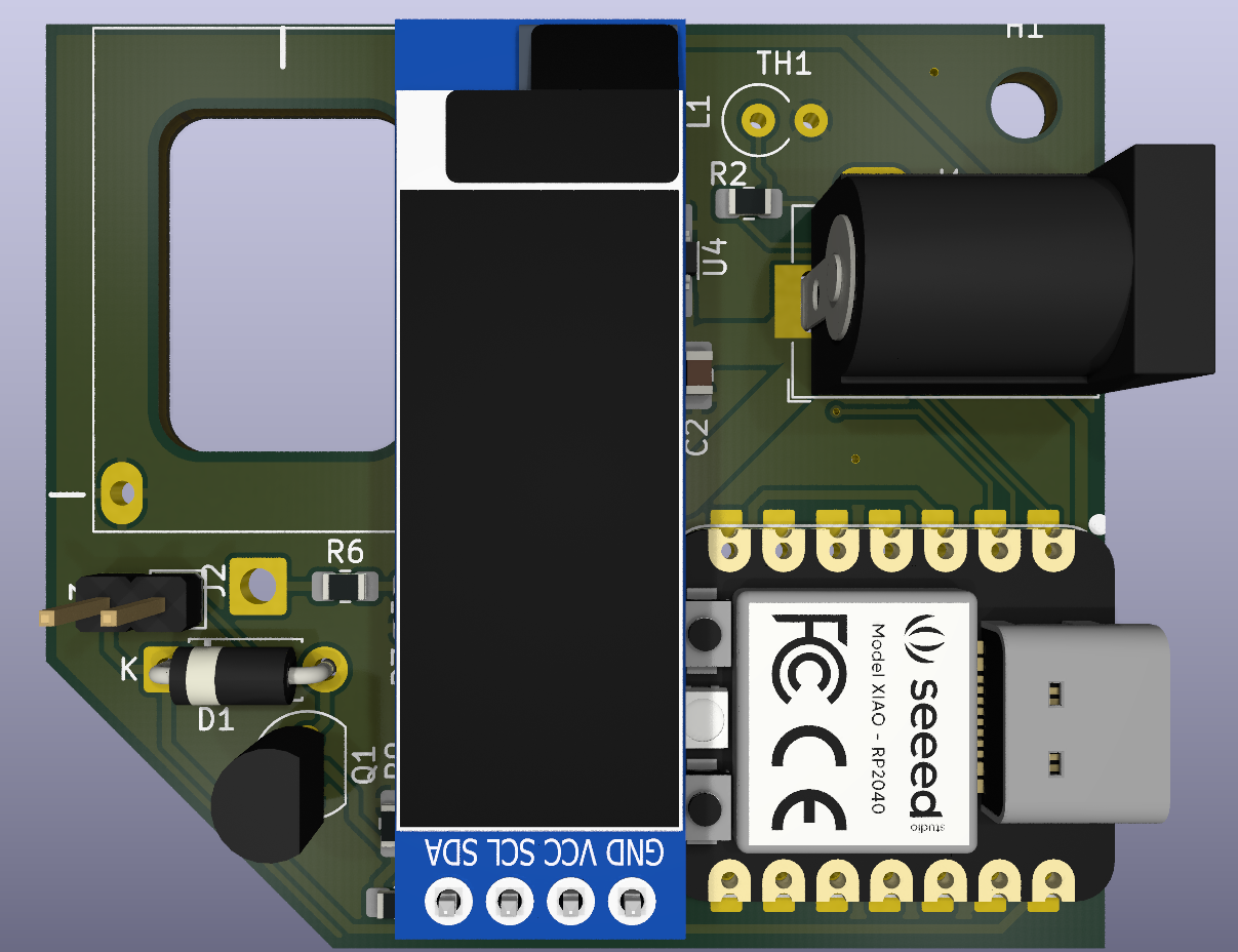
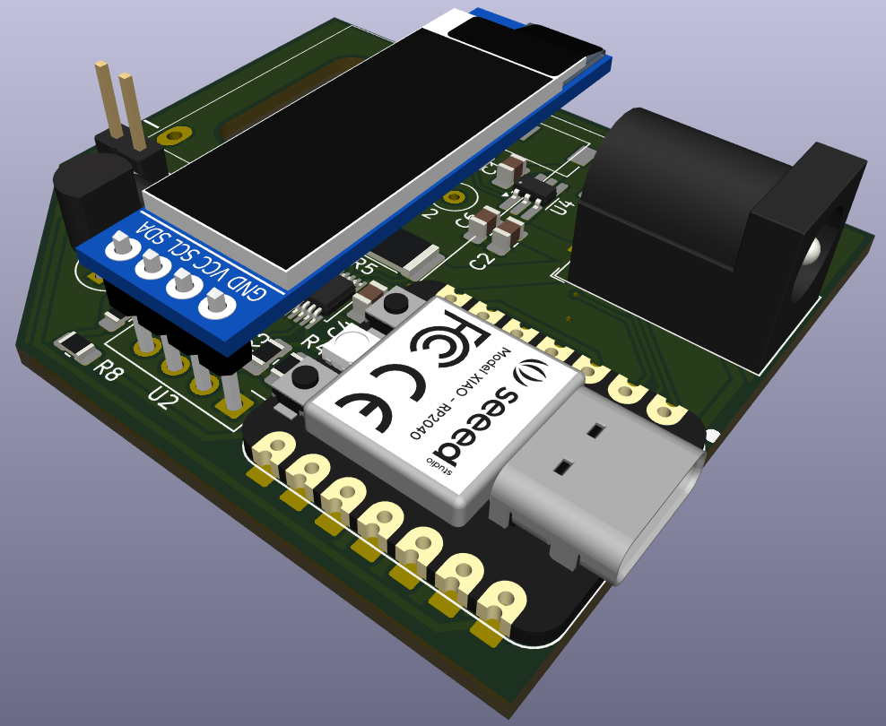
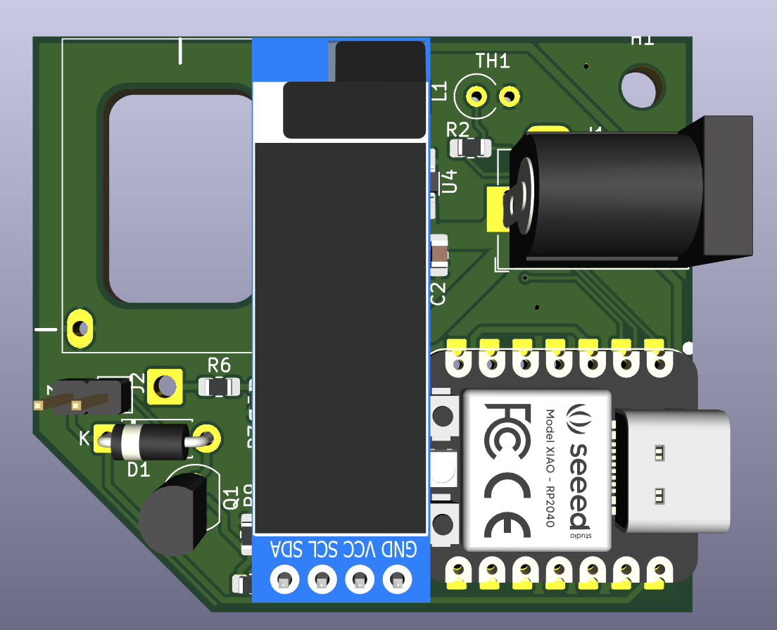
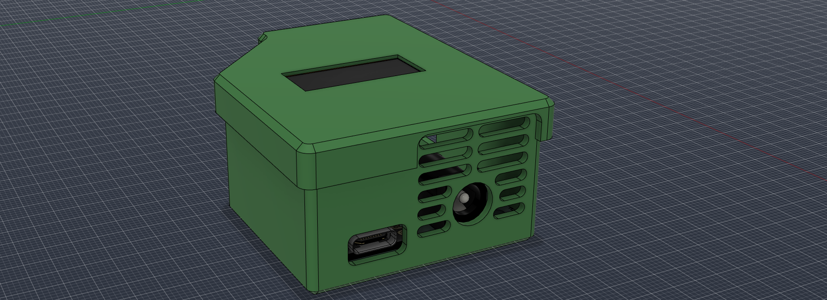
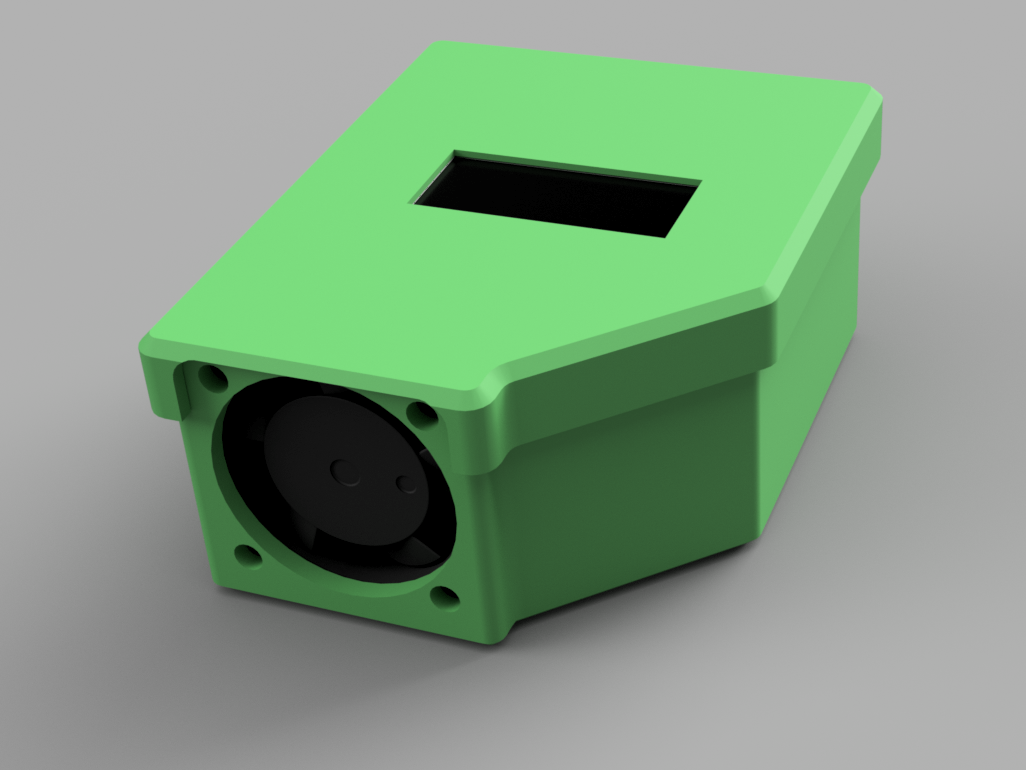
3D printable case made in Fusion 360. All CAD and 3D model files (.f3z, .step) are in the CAD/ folder.
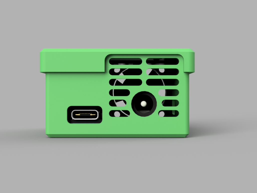
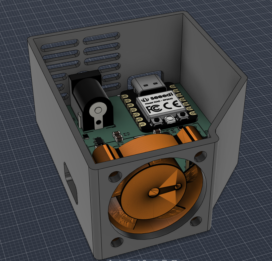
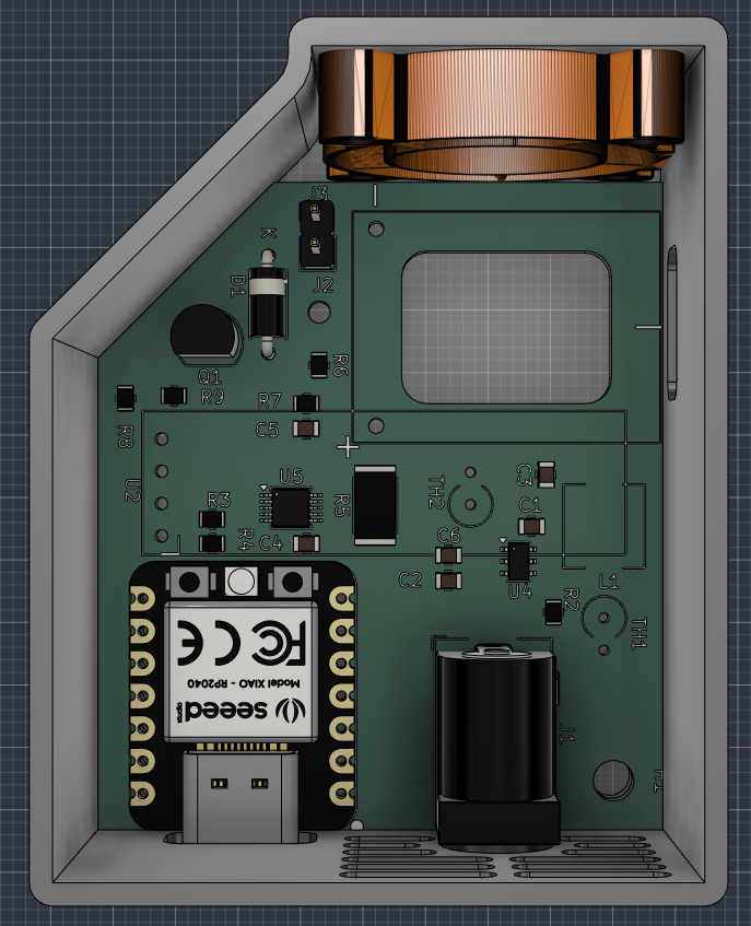
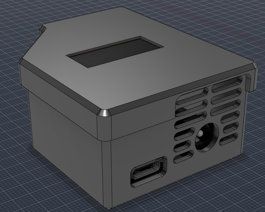
Install the following libraries in the Arduino IDE Library Manager:
Firmware/code.ino.+-----------------------+
| IN : 24.00V 3.20A | <-- DC Barrel Jack Input
| OUT: 20.00V 2.95A | <-- USB-PD Output to Device
| PWR: 62.4W | <-- Total Active Power
| T1:42C T2:36C FAN:45% | <-- Module Temp, Board Temp, Fan speed
+-----------------------+| Reference | Qty | Value / Component | Footprint / Package | Source / Link | Cost (USD) |
|---|---|---|---|---|---|
| C1, C4, C5 | 3 | 100nF 50V MLCC | 0805 SMD | TME Link | $0.65 |
| C2, C6 | 2 | 10µF 50V MLCC | 0805 SMD | TME Link | $1.10 |
| C3 | 1 | 22µF 16V MLCC | 0805 SMD | TME Link | $0.39 |
| D1 | 1 | 1N4148 Fast Switching Diode | DO-35 / DO-41 THT | TME Link | $0.1 |
| J1 | 1 | DC Barrel Jack | Horizontal THT Barrel Jack | TME Link | $2.42 |
| J3 | 1 | 2-Pin Fan Header (2.54mm) + Sunon 5V Fan | PinHeader 1x02 + 25x25x6mm Fan | TME Link | $7.90 |
| L1 | 1 | 4.7µH Power Inductor | SMD 6.3x6.3mm (LSXND6060) | TME Link | $0.50 |
| Q1 | 1 | 2N2222 NPN Transistor | TO-92 THT | TME LInk | $0.90 |
| R1, R2, R3, R4, R7, R9 | 6 | 10kΩ | 0805 SMD | TME Link | $0.084 |
| R5 | 1 | 10mΩ (0.010Ω) 1% Current Shunt | 2512 High-Power SMD | TME Link | $1.98 |
| R6 | 1 | 100kΩ 1% Resistor | 0805 SMD | TME Link | $0.070 |
| R8 | 1 | 1kΩ 1% Resistor | 0805 SMD | TME Link | $0.042 |
| TH1, TH2 | 2 | 10kΩ NTC Thermistors (B=3950) | Radial / Axial THT | TME Link | $1.45 |
| U1 | 1 | PD65W USB-C PD Step-Down Module | Custom Module Footprint | AliExpress Link | $6.00 |
| U2 | 1 | 0.91" I2C Monochrome OLED Display | 4-Pin I2C Module Header | AliExpress Link | $5.50 |
| U3 | 1 | Seeed Studio XIAO RP2040 MCU | XIAO DIP-14 Module | TME Link | $7.00 |
| U4 | 1 | AP63205WU 5V 2A Buck Regulator | TSOT-23-6 SMD | AliExpress Link | $4.00 |
| U5 | 1 | INA226AIDGSR Power Monitor IC | TSSOP-10 SMD | TME Link | $6.00 |
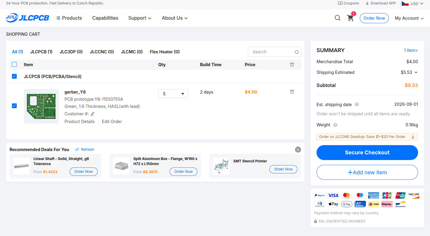
| PCB | 1 | 2-Layer Custom FR-4 PCB (1.6mm) | Custom KiCad Design | JLCPCB | $9.53 |
| Shipping | - | Combined Estimated Shipping | - | AliExpress & TME.eu | ~$10.00 |
| Total | ~$65.62 |
btw you can import every components that is from TME directly to TME cart with this file: quick_order_TME.csv
| Qty | Value | Footprint | References |
|---|---|---|---|
| 6 | R10k | Resistor_SMD:R_0805_2012Metric_Pad1.20x1.40mm_HandSolder | R1, R2, R3, R4, R7, R9 |
| 3 | 100nF | Capacitor_SMD:C_0805_2012Metric_Pad1.18x1.45mm_HandSolder | C1, C4, C5 |
| 2 | Thermistor_NTC | Resistor_THT:R_Axial_DIN0309_L9.0mm_D3.2mm_P2.54mm_Vertical | TH1, TH2 |
| 1 | 10µF 35V | Capacitor_SMD:C_0805_2012Metric_Pad1.18x1.45mm_HandSolder | C2 |
| 1 | 10µF 50V | Capacitor_SMD:C_0805_2012Metric_Pad1.18x1.45mm_HandSolder | C6 |
| 1 | 1N4148 | Diode_THT:D_DO-41_SOD81_P7.62mm_Horizontal | D1 |
| 1 | 22µF | Capacitor_SMD:C_0805_2012Metric_Pad1.18x1.45mm_HandSolder | C3 |
| 1 | 2N2222 | Package_TO_SOT_THT:TO-92 | Q1 |
| 1 | 3,3µH - 4.7µH | Inductor_SMD:L_6.3x6.3_H3 | L1 |
| 1 | AP63205WU | Package_TO_SOT_SMD:TSOT-23-6_HandSoldering | U4 |
| 1 | Barrel_Jack_MountingPin | Connector_BarrelJack:BarrelJack_Horizontal | J1 |
| 1 | FAN | Connector_PinHeader_2.54mm:PinHeader_1x02_P2.54mm_Vertical | J3 |
| 1 | INA226 | Package_SO:TSSOP-10_3x3mm_P0.5mm | U5 |
| 1 | MOUDLE-SEEEDUINO-XIAO | Seeed Studio XIAO Series Library:XIAO-RP2040-DIP | U3 |
| 1 | MountingHole | MountingHole:MountingHole_3.2mm_M3_DIN965 | H1 |
| 1 | OLED_0.91-I2C | Display:ER_OLEDM0.91_1x-I2C | U2 |
| 1 | Output_V-from-PD65 | Connector_Wire:SolderWire-1sqmm_1x01_D1.4mm_OD2.7mm | J2 |
| 1 | PD65W_module | Library_footprint:PD65W_module | U1 |
| 1 | R100k | Resistor_SMD:R_0805_2012Metric_Pad1.20x1.40mm_HandSolder | R6 |
| 1 | R10m | Resistor_SMD:R_2512_6332Metric_Pad1.40x3.35mm_HandSolder | R5 |
| 1 | R1k | Resistor_SMD:R_0805_2012Metric_Pad1.20x1.40mm_HandSolder | R8 |
VoronDesign/Voron-Tap
Tap is a nozzle-based z-probe for the V2 and Trident printer designs. The entire toolhead moves to trigger an optical switch. Tap offers many advantages:

FujiNetWIFI/fujinet-hardware
Schematics and design files for FujiNet hardware

andrekuehne/openradfan
An ESPHome-driven controller for radiator fans to improve heat output


doppelhub/Honda_Insight_LiBCM
Replacement BCM for G1 Honda Insight Lithium Conversion

GaudiLabs/qPocketPCR
Quantitative PCR machine detecting fluorescence using a camera

Qballjos/Voron-2.4-Otopus-pro-SB2209-U2C-CAN
Voron 2.4 R2 with ,Stealthburner, Voron Tap, Bambu lab Hotend. Octopus pro with TMC2209 UART, EBB SB2209 v1.0 and U2C v2.1 running klipper

ahillbom/TougherPowerMonitor-HW
Triple-channel power monitor based on INA3221 and TPS1HB08A with some filtering for tougher conditions. Compatible with Arduino Nano and Feathers.
It measures 50.9 × 44.4 mm and has 2 copper layers, 1.6 mm thick.
29 parts, built around the AP63205WU and R10M. The full list of its parts is on this page, with links to each part's symbol and footprint where PCBKit's library has them.
From the samanbeer/PD65W_Charger repository on GitHub, at the commit this page was made from: the board is PCB/PD65W_Charger.kicad_pcb and its schematic PCB/PD65W_Charger.kicad_sch. PCBKit opens the board in the browser, with nothing to install.
Its repository states no licence, so its author keeps all rights: ask samanbeer before reusing the design.