2 layers28.3 × 10.3 mm
Tap Photosensor PCB
VoronDesign/Voron-Tap
Tap is a nozzle-based z-probe for the V2 and Trident printer designs. The entire toolhead moves to trigger an optical switch. Tap offers many advantages:
12 parts716GPL-3.0

 VoronDesign/Voron-Tap716
Tap is a nozzle-based z-probe for the V2 and Trident printer designs. The entire toolhead moves to trigger an optical switch. Tap offers many advantages:
Tap Photosensor PCB is an open-source printed circuit board by VoronDesign, from the VoronDesign/Voron-Tap repository on GitHub, published under the GPL-3.0 licence. It is a 2-layer board of 28.3 × 14.3 mm with 18 parts on 14 nets, routed with 99 tracks and 14 vias.
It is built around the AP63205WU, OPB961N51 and XL-1615RGBC-RF. Its parts include 5 capacitors, 2 resistors, 2 ICs, 2 diodes and 1 connector.


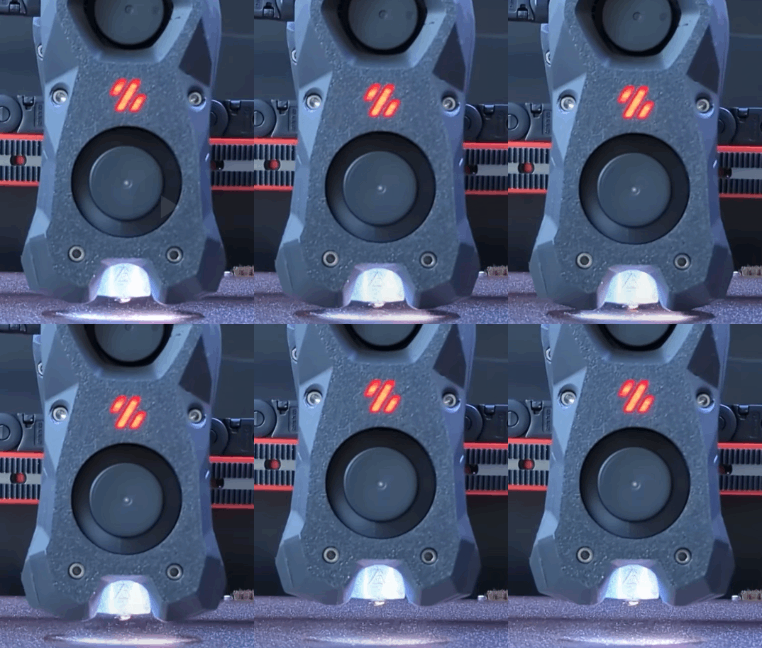
Animated image courtesy of Maple Leaf Makers , see the whole video at https://www.youtube.com/watch?v=mz5qcOZgXhI
Tap is a nozzle-based z-probe for the V2 and Trident printer designs. The entire toolhead moves to trigger an optical switch. Tap offers many advantages:
Comprehensive assembly details are available in the Manual
printer.cfg as recommended in Tap Klipper Instructionsprobe_accuracy samples=100 to "break-in" your probeprobe_accuracy checks (default of 10 probes)For well-built machines you can expect to see between 0.0000 and 0.0008 standard deviation.
Tap engineering is backed by data science. If you want to dive deeper check out the following resources:
| Qty | Value | Footprint | References |
|---|---|---|---|
| 2 | 22 µF | Capacitor_SMD:C_0603_1608Metric | C3, C5 |
| 1 | 10 µF | Capacitor_SMD:C_0805_2012Metric | C1 |
| 1 | 100 nF | Capacitor_SMD:C_0402_1005Metric | C2 |
| 1 | 200R | Resistor_SMD:R_0603_1608Metric | R1 |
| 1 | 4.7 uH | Inductor_SMD:CKCS3010 | L1 |
| 1 | 620R | Resistor_SMD:R_0603_1608Metric | R3 |
| 1 | 68 nF | Capacitor_SMD:C_0402_1005Metric | C4 |
| 1 | AP63205WU | Package_TO_SOT_SMD:TSOT-26 | U2 |
| 1 | Conn_01x03 | Connector_JST:JST_PH_S3B-PH-K_1x03_P2.00mm_Horizontal | J1 |
| 1 | D_Schottky | Diode_SMD:D_SOD-323 | D3 |
| 1 | OPB961N51 | footprints:OPTO_EE-SX398_OPB666N | U1 |
| 1 | Polyfuse_Small | Resistor_SMD:R_0805_2012Metric | F1 |
| 1 | SolderJumper_2_Bridged | Jumper:SolderJumper-2_DARKMODE | JP2 |
| 1 | SolderJumper_3_Bridged12 | Jumper:SolderJumper-3_P1.3mm_Bridged12_RoundedPad1.0x1.5mm_NumberLabels | JP1 |
| 1 | XL-1615RGBC | LED_SMD:LED_0606_1432 | D1 |
The 16 most common of 18 parts.
VoronDesign/Voron-Tap
Tap is a nozzle-based z-probe for the V2 and Trident printer designs. The entire toolhead moves to trigger an optical switch. Tap offers many advantages:

Qballjos/Voron-2.4-Otopus-pro-SB2209-U2C-CAN
Voron 2.4 R2 with ,Stealthburner, Voron Tap, Bambu lab Hotend. Octopus pro with TMC2209 UART, EBB SB2209 v1.0 and U2C v2.1 running klipper


ramalamadingdong/pcb-agent
Design a PCB end to end with an agent: CSV source of truth, idempotent build passes, containerized KiCad+Freerouting, and checks that run on the fab output.


deadbandlabs/syncro-mainboard
Hardware Design for Syncro FFB Interceptor

iotpi/KiCon2023Asia-Badge
KiCon 2023 Asia Badge © 2023 by Yang Hongbo is licensed under CC BY 4.0

jakeread/knuckles-imu-lsm6-lis2-rp2354a
This is an IMU module that pairs the LSM6DSV16X accelerometer with an LIS2MDL magnetometer, using an RP2354A microcontroller.

louisflakes/IphoneFM
KiCad project for IphoneFM Rev A. Built step by step from ../../design/rev-a/kicad-build-procedure.md; checked with ../../tools/kicadcheck.py.
It measures 28.3 × 14.3 mm and has 2 copper layers, 1.6 mm thick.
18 parts, built around the AP63205WU, OPB961N51 and XL-1615RGBC-RF. The full list of its parts is on this page, with links to each part's symbol and footprint where PCBKit's library has them.
From the VoronDesign/Voron-Tap repository on GitHub, at the commit this page was made from: the board is OptoTap/Tap_Photosensor_PCB_v2/Tap_Photosensor_PCB.kicad_pcb and its schematic OptoTap/Tap_Photosensor_PCB_v1/Tap_Photosensor_PCB.kicad_sch. PCBKit opens the board in the browser, with nothing to install.
Its repository publishes it under the GPL-3.0 licence: you may reuse it on that licence's terms (keep the author's notice, and for a copyleft licence share your changes alike).