2 layers102.5 × 76.6 mm
IC 002 - Acoustic Nb IoT Daughter Board
ryanstevensmith/locust_hardware
The electronics repository for the locust project by Imperial College
76 partsCERN-OHL-P-2.0

 ryanstevensmith/locust_hardware
The electronics repository for the locust project by Imperial College
IC 001 - Low Cost Audio Sensor is an open-source printed circuit board by ryanstevensmith, from the ryanstevensmith/locust_hardware repository on GitHub, published under the CERN-OHL-P-2.0 licence. It is a 4-layer board of 115 × 107 mm with 174 parts on 133 nets, routed with 1,333 tracks and 292 vias.
It is built around the ESP32-S3-WROOM-1-N8, TLV320ADC3101IRGER and TPS63000DRC, with the BQ27427YZF, SPV0142LR5H-1 and TL3305AF260QG among its other parts. Its parts include 53 diodes, 31 resistors, 23 capacitors, 8 ICs and 8 connectors. It belongs with the audio and music and sensors and measurement boards and the ESP32 boards of this library.


Open hardware for Locust, a low-cost acoustic monitoring sensor developed with Imperial College London. It records audio to a microSD card in the field and can optionally send data over NB-IoT through a plug-in daughter board.
This repository contains the KiCad design files, manufacturing outputs and a firmware flashing tool for the electronics.
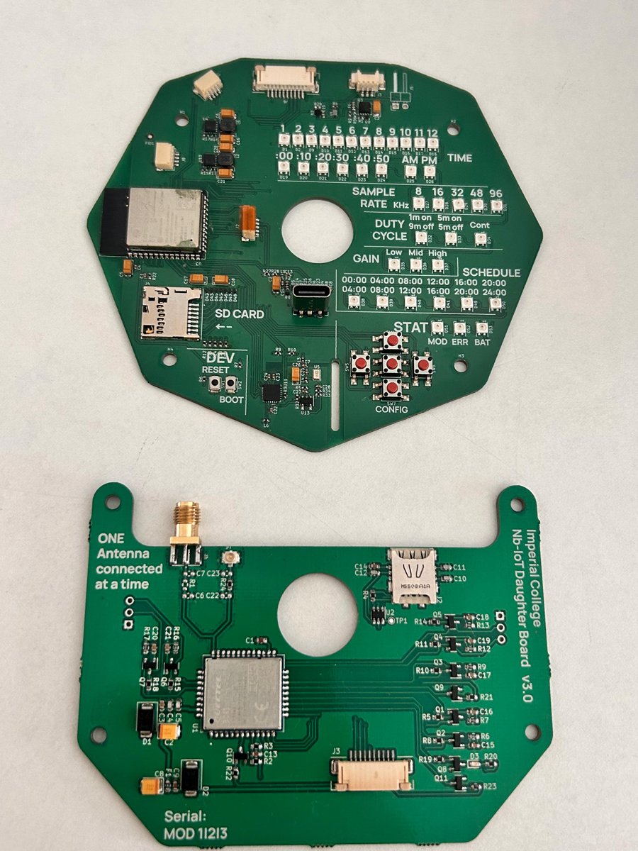
| Board | Description | Latest release |
|---|---|---|
| IC_001 - Low Cost Audio Sensor | Main board: ESP32-S3 audio recorder with microSD storage and Li-ion battery management | v3.0 |
| IC_002 - Acoustic Nb-IoT Daughter Board | Optional NB-IoT add-on board for sending data off the device | v3.0 |
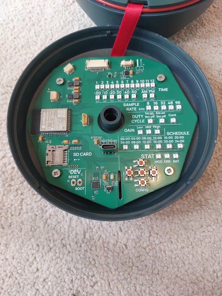
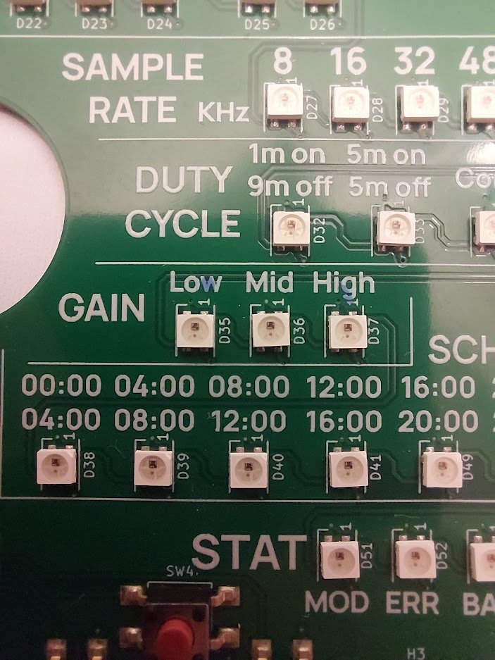
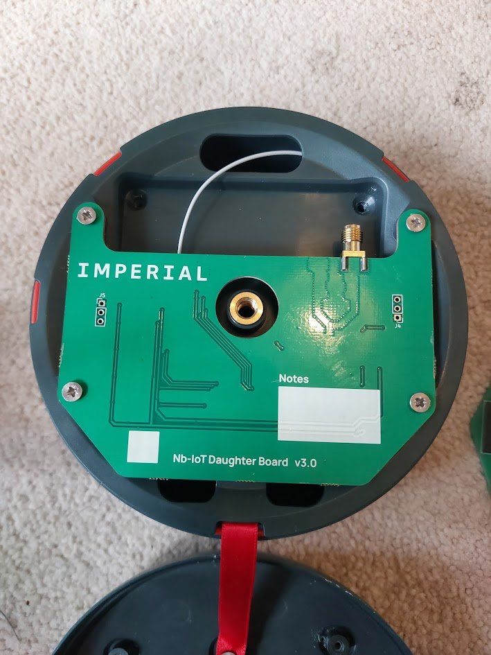
Each board follows the same structure:
IC_00X - <Board Name>/
  working/                              KiCad project (in-progress design)
  IC_00X - <Board Name> - Release vX.Y/
    ... - Schematics - vX.Y.pdf
    ... - Layer Drawings - vX.Y.pdf
    ... - vX.Y.step                     3D model of the assembled board
    ... - proj files - vX.Y.zip         KiCad project snapshot for this release
    front.png / back.png                Board renders
    manufacturing files/
      BoM / PnP (JLC and EXT)           Bill of materials and pick-and-place files
      <gerber folders and zip>          Gerbers (RS-274X and X2) and drill files
firmware/                               Pre-built test firmware binaries
uploader/                               Windows flashing tool (Python source)
JLC files are formatted for JLCPCB assembly (LCSC part numbers). EXT files are for any other assembler and list manufacturer and Digi-Key part numbers.
Use the v3.0 releases for new builds. The v1.0 releases are kept for reference.
A complete unit needs:
| Item | Part |
|---|---|
| Main board | IC_001 v3.0 |
| NB-IoT board (optional) | IC_002 v3.0 |
| Board-to-board cable | Molex 15167-0250 FFC |
| Antenna | KYOCERA AVX 9000440F0-AA12L0150 (U.FL) |
| Battery | 3× 18650 cells in parallel (1S3P), see below |
| Enclosure | Injection-moulded enclosure, not included in this repo |
⚠️ Check the polarity before connecting. Many off-the-shelf PicoBlade battery leads are wired the other way round.
Pre-built test firmware is in firmware/. The firmware source code is not part of this repository.
updater.exe in the same folder as bootloader.bin, partitions.bin and firmware.bin.updater.exe. The tool is unsigned, so if Windows SmartScreen warns you, click More info → Run anyway.If the board isn't detected, hold BOOT, press RESET, then release BOOT to enter download mode.
pip install esptool
esptool.py --chip esp32s3 --port <PORT> --baud 460800 write_flash -z \
  0x0 bootloader.bin \
  0x8000 partitions.bin \
0x10000 firmware.bincd uploader
pip install -r requirements.txt pyinstaller
pyinstaller updater.specThe executable is written to uploader/dist/updater.exe.
SR_* library, which is not included. KiCad stores footprints inside the board file and symbols inside the schematic, so the projects open and can be edited without that library. Library paths use the ${SR_KICAD_LIB} path variable.The hardware designs are released under the CERN Open Hardware Licence Version 2 – Permissive (CERN-OHL-P-2.0).
The updater software in uploader/ is released under the MIT License.
Copyright © 2026 Ryan Smith.
Designed by Smith Robotics for Imperial College London.
| Qty | Value | Footprint | References |
|---|---|---|---|
| 40 | SK6806 - j | SR_LED:LED_SK6805_PLCC4_2.4x2.7mm_P1.3mm | D1, D2, D10, D11, D12, D13, D14, D15, D16, D17, D18, D19, D20, D21, D22, D23 +24 |
| 27 | TestPoint | TestPoint:TestPoint_Pad_D1.0mm | TP1, TP2, TP10, TP11, TP12, TP13, TP14, TP15, TP16, TP17, TP18, TP19, TP20, TP21, TP22, TP23 +11 |
| 12 | 10K | Resistor_SMD:R_0402_1005Metric | R1, R4, R6, R7, R9, R10, R12, R13, R14, R18, R19, R27 |
| 12 | ESD761 | SR_Package_SON:Texas_DPY0002A_0.6x1mm_P0.65mm | D4, D5, D6, D7, D8, D42, D43, D44, D45, D46, D47, D48 |
| 11 | 100nF | Capacitor_SMD:C_0402_1005Metric | C1, C4, C7, C8, C13, C22, C23, C24, C25, C27, C28 |
| 10 | 10uF | Capacitor_Tantalum_SMD:CP_EIA-3216-18_Kemet-A | C2, C3, C5, C6, C16, C17, C18, C20, C21, C26 |
| 5 | TL3305AF260QG | SR_Button:SW_SPST_TL3305A | SW4, SW5, SW6, SW7, SW8 |
| 4 | BLM15PX221SN1D | Inductor_SMD:L_0402_1005Metric | L1, L3, L4, L6 |
| 4 | M3 | MountingHole:MountingHole_3.2mm_M3 | H1, H2, H3, H4 |
| 3 | 0R | Resistor_SMD:R_0402_1005Metric | R2, R3, R30 |
| 3 | 1M | Resistor_SMD:R_0402_1005Metric | R8, R11, R22 |
| 3 | 47K | Resistor_SMD:R_0402_1005Metric | R5, R32, R33 |
| 2 | 180K | Resistor_SMD:R_0402_1005Metric | R15, R17 |
| 2 | 1A/6V | Fuse:Fuse_0603_1608Metric | F1, F2 |
| 2 | 2.2uH | Inductor_SMD:L_Bourns-SRN4018 | L2, L5 |
| 2 | 22R | Resistor_SMD:R_0402_1005Metric | R25, R26 |
| 2 | 5K1 | Resistor_SMD:R_0402_1005Metric | R23, R24 |
| 2 | Fiducial | Fiducial:Fiducial_1mm_Mask2mm | FID1, FID2 |
| 2 | JST_SH | SR_Connectors:JST_SH_SM04B-SRSS-TB_1x04-1MP_P1.00mm_Horizontal | J7, J8 |
| 2 | SW_Push | Button_Switch_SMD:SW_SPST_B3U-1000P | SW1, SW2 |
| 2 | TPS63000 | Package_SON:Texas_DRC0010J_ThermalVias | U4, U10 |
| 1 | 10n | Capacitor_SMD:C_0402_1005Metric | C14 |
| 1 | 1M6 | Resistor_SMD:R_0402_1005Metric | R16 |
| 1 | 1M8 | Resistor_SMD:R_0402_1005Metric | R29 |
| 1 | 220R | Resistor_SMD:R_0402_1005Metric | R34 |
| 1 | 2u2 | Capacitor_SMD:C_0402_1005Metric | C15 |
| 1 | 4K7 | Resistor_SMD:R_0402_1005Metric | R28 |
| 1 | 503398-1892 | SR_Connectors:503398-1892 | J4 |
| 1 | 52207-1060 | SR_Connectors:52207-1060 | J6 |
| 1 | 53261-0371 | Connector_Molex:Molex_PicoBlade_53261-0371_1x03-1MP_P1.25mm_Horizontal | J3 |
| 1 | BQ21080 | SR_Package_BGA:Texas_DSBGA-8-1.6mmx1mm_P0.4mm | U1 |
| 1 | BQ27427 | SR_Package_BGA:Texas_DSBGA-9-1.6mmx1.6_P0.5mm | U2 |
| 1 | BZT52C6V8LP-7 | SR_Package_DFN_QFN:X1-DFN1006-2 | D3 |
| 1 | Conn_01x02_Pin | Connector_PinHeader_2.54mm:PinHeader_1x02_P2.54mm_Horizontal | J5 |
| 1 | DMP3013SFV | Package_SON:Diodes_PowerDI3333-8 | Q3 |
| 1 | ESP32-S3-WROOM-1 | RF_Module:ESP32-S3-WROOM-1 | U3 |
| 1 | JST_SH | SR_Connectors:JST_SH_BM05B-SRSS-TB_1x05-1MP_P1.00mm_Vertical | J2 |
| 1 | LOGO | SR_Logos_Images:SR | G*** |
| 1 | LOGO | SR_Logos_Images:Imperial_4mmx36mm | G*** |
| 1 | OPA1671IDBVR | Package_TO_SOT_SMD:TSOT-23-5 | U13 |
| 1 | SPV0142LR5H | SR_Sensor_Audio:SPV0142LR5H-1 | U5 |
| 1 | TLV320ADC3101IRGER | Package_DFN_QFN:QFN-24-1EP_4x4mm_P0.5mm_EP2.8x2.8mm | U11 |
| 1 | USB4115-03-C | SR_Connectors:USB_C_Receptacle_GCT_USB4115-03-C | J1 |
ryanstevensmith/locust_hardware
The electronics repository for the locust project by Imperial College


Alli-Ekundayo/scpt-rl
SCPT-RL trains a cross-attention transformer policy to place PCB components sequentially on a discrete grid. Training has two phases:

shubhisgonnastealyourcode/FT-32-esp32-s3-dev-board-
Custom ESP32-S3 Development Board with Header Pins for Display and RGB LED

EmpiricalEE/uUSB-FP
The uUSB FP is a versatile panel for the Joulescope JS220 power analyser that enables power measurement of any USB device.


CoolNamesAllTaken/vibamix
An interactive ePaper nametage for playing "will it blend" with arbitrary groups of people.


Protocentral/healthypi-move-hw
Hardware files for the HealthyPi Move
It measures 115 × 107 mm and has 4 copper layers, 1.6 mm thick.
174 parts, built around the ESP32-S3-WROOM-1-N8, TLV320ADC3101IRGER, TPS63000DRC and BQ27427YZF. The full list of its parts is on this page, with links to each part's symbol and footprint where PCBKit's library has them.
From the ryanstevensmith/locust_hardware repository on GitHub, at the commit this page was made from: the board is IC_001 - Low Cost Audio Sensor/working/IC_001 - Low Cost Audio Sensor.kicad_pcb and its schematic IC_001 - Low Cost Audio Sensor/working/IC_001 - Low Cost Audio Sensor.kicad_sch. PCBKit opens the board in the browser, with nothing to install.
Its repository publishes it under the CERN-OHL-P-2.0 licence: you may reuse it on that licence's terms (keep the author's notice, and for a copyleft licence share your changes alike).