2 layers57 × 85 mm
 JungleGim/PyDash_PCB
The circuit board portion for PyDash
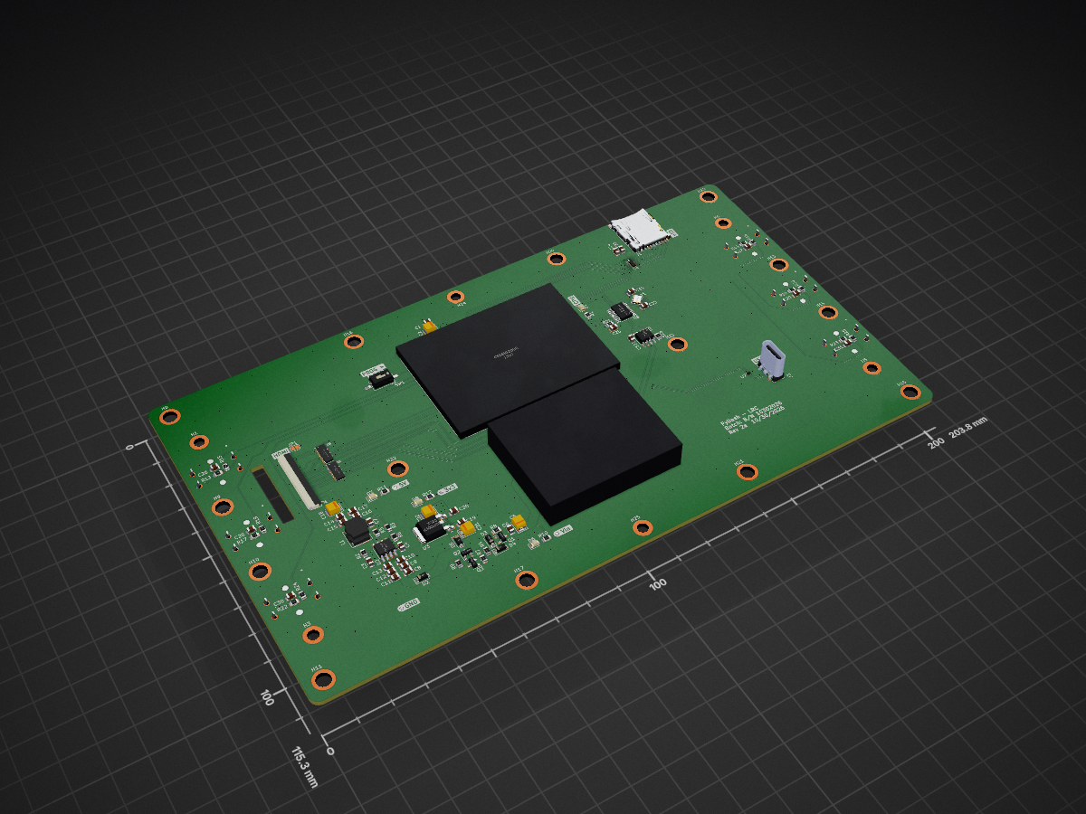
Py dash pcb 7 is an open-source printed circuit board by JungleGim, from the JungleGim/PyDash_PCB repository on GitHub. It is a 4-layer board of 203.8 × 115.3 mm with 120 parts on 212 nets, routed with 782 tracks and 494 vias.
It is built around the SN65HVD231D, TPD8S009DSMR and NCV1117DT33T5G, with the EMIF06-MSD02N16, TPD2E009DRTR and SMTSO-M25-6ET among its other parts. Its parts include 34 capacitors, 26 resistors, 9 ICs, 9 diodes and 7 switches.


This readme covers the printed circuit board or PCB portion of the PyDash. For the App design, Enclosure design, or OS design, see the below repositories:
The PyDash_PCB is a daughter board that contains the hardware required for a rPi compute module (CM4) to function as a processor to display information on a 7in screen.
Additional details on the design considerations, required packages, and key features are included in the "Methodology" section of this readme.
TBD: quick detail starting with the arduino + daughter board on the 5in display as a proof of concept
The following sections are some notes on the various considerations or any constraints when designing the display.
As built, with the sourced display and components in the BOM, the display uses approximately 350-400mA when operation, at 100% backlight.
The chosen display is a 7inch 1024x600 IPS display sourced from waveshare link. The display is fastened to the carrier PCB via double-sided foam tape. The 40pin FPC jack directly connects to the HDMI output from the CM4.
To control the backlight via PWM, drive the "BL_en" pin high. The PWM signal is scaled from 1024 (100%) to 0 (0) for brightest to darkest.
Any HDMI compatable display should be able to be used with this design. While the FPC cable was a design choice, any other HDMI connection should be appropriate, depending on the chosen display.
Additional considerations for the HDMI hardware and driver configuration is contained in the "PyDash OS" readme.
JLC PCB stackups for TDMS impedence considerations
Chosen stackup: JLC04121H-3313 – 1oz (0.035mm) outer layer
Other available options with calculated requirements
No current known bugs
No current FAQ
This program is free software: you can redistribute it and/or modify it under the terms of the GNU General Public License as published by the Free Software Foundation, either version 3 of the License, or (at your option) any later version.
This program is distributed in the hope that it will be useful, but WITHOUT ANY WARRANTY; without even the implied warranty of MERCHANTABILITY or FITNESS FOR A PARTICULAR PURPOSE. See the GNU General Public License for more details.
You should have received a copy of the GNU General Public License along with this program. If not, see https://www.gnu.org/licenses/.
The information included is provided "as is", without warranty of any kind, express or implied, including but not limited to the warranties of merchantability, fitness for a particular purpose and non-infringement. In no event shall the authors or copyright holders be liable for any claim, damages or other liability, whether in an action of contract, tort or otherwise, arising from, out of or in connection with the software or the use or other dealings in the software or tools included in this repository.
While I am an engineer by trade, my area of focus is not computer architecture or system engineering. Likely some people have already looked at various aspects of the codebase and just shook their heads. That being said, I've compiled a list of considerations and notes for the project that have helped me along the way. These are listed below, in no particular order.
Throughout the project, I have used many references, related to various aspects/items of the project. These are all compiled in the list below, in no particular order
| Qty | Value | Footprint | References |
|---|---|---|---|
| 14 | Standoff_M2.5_6ET | user:Standoff_M2.5_6ET | H8, H9, H10, H11, H12, H13, H14, H15, H16, H17, H20, H21, H22, H23 |
| 11 | 10k | Resistor_SMD:R_0805_2012Metric | R4, R7, R8, R9, R13, R14, R17, R18, R21, R22, R23 |
| 11 | 10u | Capacitor_SMD:C_0805_2012Metric | C8, C9, C10, C11, C12, C13, C14, C15, C16, C17, C24 |
| 10 | 1u | Capacitor_SMD:C_0805_2012Metric | C1, C6, C19, C20, C26, C27, C28, C29, C30, C31 |
| 6 | 27k | Resistor_SMD:R_0805_2012Metric | R15, R16, R19, R20, R24, R25 |
| 6 | MountingHole_M2 | MountingHole:MountingHole_3.2mm_M3_DIN965_Pad_TopOnly | H1, H3, H5, H6, H24, H25 |
| 6 | SW_Push | user:SW_B3F-4050_OMR | SW2, SW3, SW4, SW5, SW6, SW7 |
| 5 | 0u1 | Capacitor_SMD:C_0805_2012Metric | C3, C4, C23, C25, C32 |
| 4 | 10u_25v | Capacitor_Tantalum_SMD:CP_EIA-3528-21_Kemet-B | C2, C5, C21, C22 |
| 4 | red | LED_SMD:LED_0805_2012Metric | D1, D6, D7, D8 |
| 3 | DMG2307 | Package_TO_SOT_SMD:SOT-23 | Q1, Q2, Q3 |
| 2 | 20p | Capacitor_SMD:C_0805_2012Metric | C33, C34 |
| 2 | 27V | Diode_SMD:D_SOD-123 | D4, D5 |
| 2 | 2A 60V | Diode_SMD:D_SOD-123 | D2, D3 |
| 2 | 660r | Resistor_SMD:R_0805_2012Metric | R1, R12 |
| 2 | TPD8S009DSMR | user:IC_TPD8S009DSMR | U5, U6 |
| 1 | 100u | Capacitor_Tantalum_SMD:CP_EIA-3528-21_Kemet-B | C18 |
| 1 | 10r | Resistor_SMD:R_0805_2012Metric | R2 |
| 1 | 12k 1% | Resistor_SMD:R_0805_2012Metric | R3 |
| 1 | 16Mhz | Crystal:Crystal_SMD_3225-4Pin_3.2x2.5mm | Y1 |
| 1 | 1k | Resistor_SMD:R_0805_2012Metric | R11 |
| 1 | 1n2 | Capacitor_SMD:C_0805_2012Metric | C7 |
| 1 | 20k 1% | Resistor_SMD:R_0805_2012Metric | R5 |
| 1 | 2k2 1% | Resistor_SMD:R_0805_2012Metric | R6 |
| 1 | 2k7 | Resistor_SMD:R_0805_2012Metric | R10 |
| 1 | 3h3 | Inductor_SMD:L_Bourns_SRN6045TA | L1 |
| 1 | 4k7 | Resistor_SMD:R_0805_2012Metric | R26 |
| 1 | AP64501SP-13 | user:SOIC127P600X170-9N | U2 |
| 1 | BD33FC0FP | Package_TO_SOT_SMD:TO-252-2 | U3 |
| 1 | CANbus | user:DT13-4P | J4 |
| 1 | CM4102008 | user:MODULE_CM4102008 | U1 |
| 1 | EMIF06-MSD02N16 | user:EMIF06MSD02N16 | U4 |
| 1 | FFC2B28-40-G | user:GCT_FFC2B28-40-G | J2 |
| 1 | MCP2515-xST | Package_SO:TSSOP-20_4.4x6.5mm_P0.65mm | U8 |
| 1 | Micro_SD_Card_Det1 | Connector_Card:microSD_HC_Hirose_DM3AT-SF-PEJM5 | J1 |
| 1 | NUP2105L | Package_TO_SOT_SMD:SOT-23 | D9 |
| 1 | NetTie_2 | user:NetTie-2_SMD_Pad0.2mm | NT1 |
| 1 | SN65HVD231 | Package_SO:SOIC-8_3.9x4.9mm_P1.27mm | U9 |
| 1 | TPD2EUSB30 | Package_TO_SOT_SMD:Texas_DRT-3 | U7 |
| 1 | TP_12V | TestPoint:TestPoint_Pad_D1.0mm | TP3 |
| 1 | TP_3v3 | TestPoint:TestPoint_Pad_D1.0mm | TP1 |
| 1 | TP_5V | TestPoint:TestPoint_Pad_D1.0mm | TP2 |
| 1 | TP_GND | TestPoint:TestPoint_Pad_D1.0mm | TP4 |
| 1 | USB_C_Receptacle_USB2.0_14P | Connector_USB:USB_C_Receptacle_GCT_USB4115-03-C | J3 |
| 1 | nBoot | Button_Switch_SMD:SW_DIP_SPSTx01_Slide_6.7x4.1mm_W8.61mm_P2.54mm_LowProfile | SW1 |
| 1 | p18_jmp | Jumper:SolderJumper-2_P1.3mm_Open_RoundedPad1.0x1.5mm | JP1 |

nherbaut/pico-power-sensor
This board sockets a Pico 2 W, provides five programmable green LEDs and a microSD slot, and connects to the INA229EVM through a left-edge right-angle socket.

bernardopg/ps28-modern-amp
Infinity Primus PS28 amplifier modernization: TPA3255 engineering, validation and safety-gated workflow


imnotjames/framework-laptop-projects
The framework laptop uses the I-PEX Cabline-UM 20879-040E-01 for interacting with the eDP port - and I want to use it for things other than the framework laptop display kit.

antmicro/gpu-cluster-backplane
This project contains open hardware design files for a PCB supporting power distribution in a cluster composed of GPUs. This board has been derived from an open source d1600e-psu-breakout created by Antmicro.
It measures 203.8 × 115.3 mm and has 4 copper layers, 1.6 mm thick.
120 parts, built around the SN65HVD231D, TPD8S009DSMR, NCV1117DT33T5G and EMIF06-MSD02N16. The full list of its parts is on this page, with links to each part's symbol and footprint where PCBKit's library has them.
From the JungleGim/PyDash_PCB repository on GitHub, at the commit this page was made from: the board is PCB_files/py_dash_pcb_7.kicad_pcb and its schematic PCB_files/ext_cons.kicad_sch. PCBKit opens the board in the browser, with nothing to install.
Its repository states no licence, so its author keeps all rights: ask JungleGim before reusing the design.