4 layers75 × 42 mm
Xmit
tdunning/xmit
A simple low-power digital transmitter for amateur bands using new components
87 parts3

 rudy1904/hushlog
-channel, 24-bit data logger for small, slow signals: thermocouples, strain gauges, photodiodes and RTDs.
Hushlog is an open-source printed circuit board by rudy1904, from the rudy1904/hushlog repository on GitHub. It is a 2-layer board of 80 × 60 mm with 71 parts on 69 nets, routed with 495 tracks and 198 vias.
It is built around the RP2040, ADS1220IPW and W25Q128JVSIQ, with the AP2112K-3.3 and TPS7A2033PDBV among its other parts. Its parts include 30 capacitors, 20 resistors, 8 connectors, 5 ICs and 2 switches. It belongs with the sensors and measurement boards and the RP2040 boards of this library.


A 4-channel, 24-bit data logger for small, slow signals - thermocouples, strain gauges, photodiodes, RTDs.
Most DIY loggers read tiny voltages with the microcontroller's built-in ADC, which is fine until the signal is small, at which point it's mostly noise. Hushlog uses a real 24-bit precision ADC (the TI ADS1220) with differential input channels, read by a bare RP2040, logged to a microSD card, with a small OLED for live readings - all on a custom 2-layer board.
The thing I care about most is keeping it quiet: a separate low-noise supply for the analog side, RC filtering on every input, and a layout that keeps the digital switching noise away from the ADC. The plan is to short the inputs, measure the noise floor, and compare it to the datasheet - that number goes in this repo, good or bad.
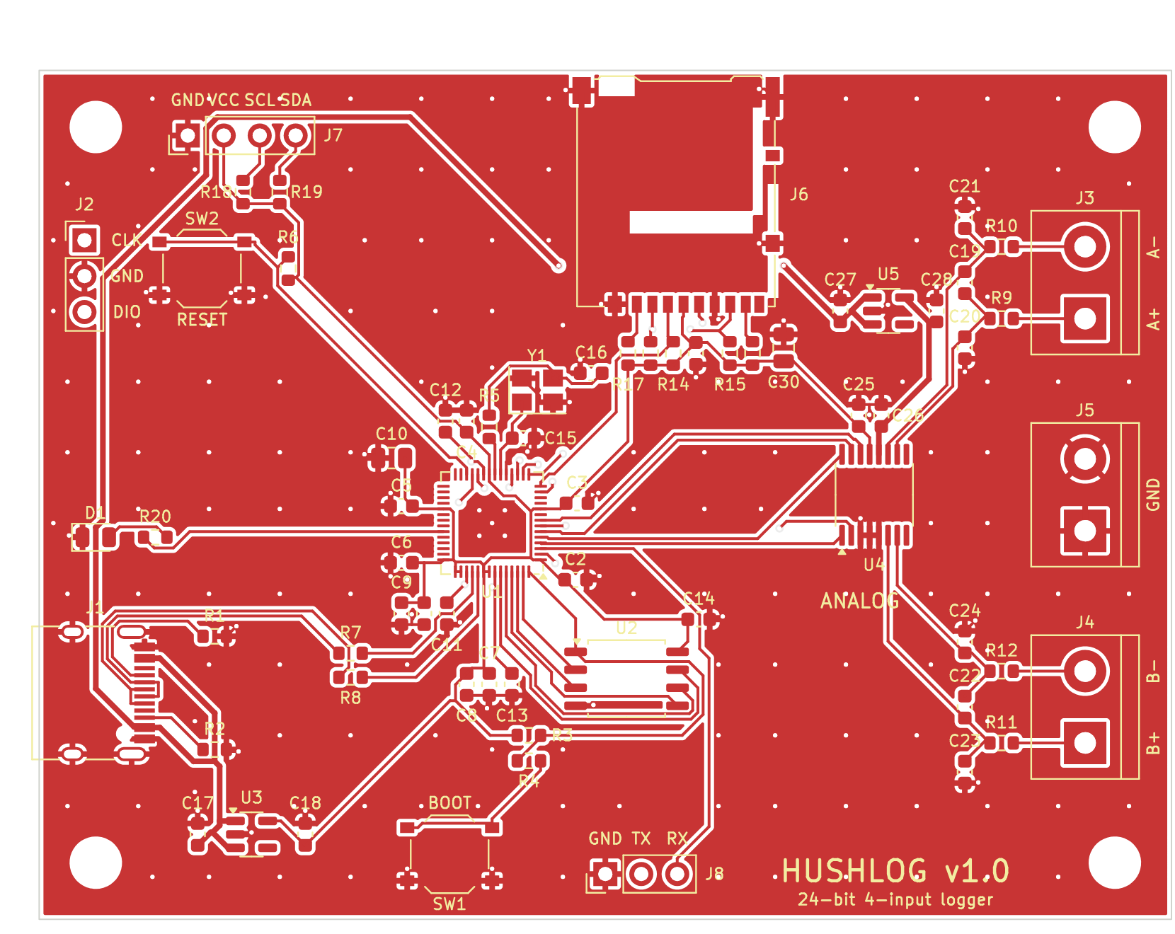
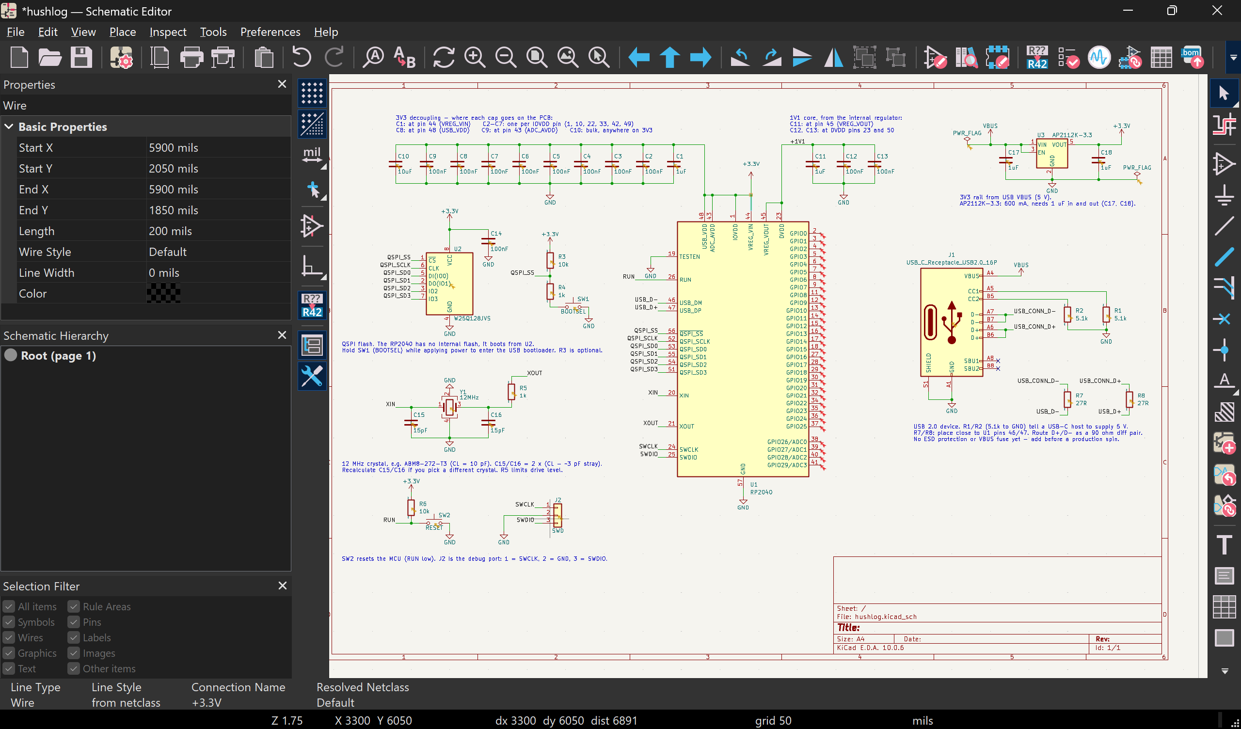
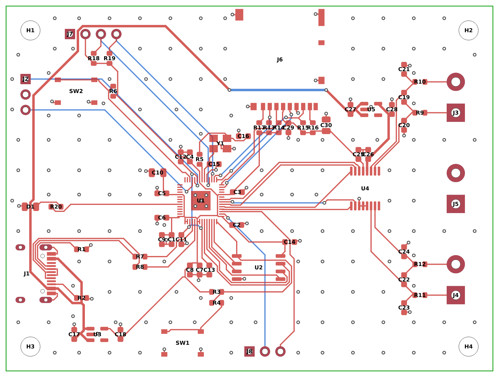
| Folder | What's in it |
|---|---|
hardware/ | KiCad 10 project - schematic + PCB |
firmware/ | RP2040 test firmware (PlatformIO / Arduino-Pico) |
fab/ | Gerbers, drill files, placement, fabrication BOM |
docs/ | Schematic render and board images |
reports/ | ERC and DRC reports |
Design complete for the Hack Club Half Life warm-up (Tier 2).
See firmware/README.md. It's a bring-up test: it
configures the ADS1220, reads two differential channels, and streams the
readings over USB serial, SD and the OLED. Written for the Arduino-Pico core,
built with PlatformIO.
Headline parts (full list in BOM.md and fab/):
| Part | Role |
|---|---|
| RP2040 | microcontroller |
| W25Q128 | QSPI boot flash |
| ADS1220 | 24-bit ADC |
| AP2112K-3.3 | 3.3V LDO (digital) |
| TPS7A2033 | low-noise LDO (analog) |
| SSD1306 0.96" | OLED display |
Note: SD writes and OLED refreshes should be held off during ADC conversions to keep them out of the noise floor - handled in the real logging loop, flagged in the firmware TODO.
| Qty | Value | Footprint | References |
|---|---|---|---|
| 16 | 100nF | Capacitor_SMD:C_0603_1608Metric | C2, C3, C4, C5, C6, C7, C8, C9, C12, C13, C14, C19, C22, C25, C26, C29 |
| 7 | 10k | Resistor_SMD:R_0603_1608Metric | R3, R6, R13, R14, R15, R16, R17 |
| 7 | 1k | Resistor_SMD:R_0603_1608Metric | R4, R5, R9, R10, R11, R12, R20 |
| 6 | 1uF | Capacitor_SMD:C_0603_1608Metric | C1, C11, C17, C18, C27, C28 |
| 4 | 10nF | Capacitor_SMD:C_0603_1608Metric | C20, C21, C23, C24 |
| 4 | M3 | MountingHole:MountingHole_3.2mm_M3 | H1, H2, H3, H4 |
| 2 | 10uF | Capacitor_SMD:C_0805_2012Metric | C10, C30 |
| 2 | 15pF | Capacitor_SMD:C_0603_1608Metric | C15, C16 |
| 2 | 27R | Resistor_SMD:R_0603_1608Metric | R7, R8 |
| 2 | 4.7k | Resistor_SMD:R_0603_1608Metric | R18, R19 |
| 2 | 5.1k | Resistor_SMD:R_0603_1608Metric | R1, R2 |
| 1 | 12MHz | Crystal:Crystal_SMD_Abracon_ABM8G-4Pin_3.2x2.5mm | Y1 |
| 1 | ADS1220IPW | Package_SO:TSSOP-16_4.4x5mm_P0.65mm | U4 |
| 1 | AP2112K-3.3 | Package_TO_SOT_SMD:SOT-23-5 | U3 |
| 1 | BOOTSEL | Button_Switch_SMD:SW_Push_1P1T_XKB_TS-1187A | SW1 |
| 1 | GND | TerminalBlock:TerminalBlock_bornier-2_P5.08mm | J5 |
| 1 | IN_A | TerminalBlock:TerminalBlock_bornier-2_P5.08mm | J3 |
| 1 | IN_B | TerminalBlock:TerminalBlock_bornier-2_P5.08mm | J4 |
| 1 | LED | LED_SMD:LED_0805_2012Metric | D1 |
| 1 | Micro_SD_Card | Connector_Card:microSD_HC_Hirose_DM3AT-SF-PEJM5 | J6 |
| 1 | OLED | Connector_PinHeader_2.54mm:PinHeader_1x04_P2.54mm_Vertical | J7 |
| 1 | RESET | Button_Switch_SMD:SW_Push_1P1T_XKB_TS-1187A | SW2 |
| 1 | RP2040 | Package_DFN_QFN:QFN-56-1EP_7x7mm_P0.4mm_EP3.2x3.2mm | U1 |
| 1 | SWD | Connector_PinHeader_2.54mm:PinHeader_1x03_P2.54mm_Vertical | J2 |
| 1 | TPS7A2033PDBV | Package_TO_SOT_SMD:SOT-23-5 | U5 |
| 1 | UART | Connector_PinHeader_2.54mm:PinHeader_1x03_P2.54mm_Vertical | J8 |
| 1 | USB_C_Receptacle_USB2.0_16P | Connector_USB:USB_C_Receptacle_HRO_TYPE-C-31-M-12 | J1 |
| 1 | W25Q128JVS | Package_SO:SOIC-8_5.3x5.3mm_P1.27mm | U2 |
tdunning/xmit
A simple low-power digital transmitter for amateur bands using new components

LollobolUni/muon-time-dilation
A self-built experiment to measure the lifetime of cosmic-ray muons and to show, with data taken from cable cars in the Alps, that moving clocks run slow.

SethTheDev/Resonance
A powerful STM32F411-based USB audio interface rocking a Cirrus Logic DAC with DSP


matthewgpetrin/odc-cc2500
Simple breakout board for the CC2500. To be incorporated into more ambitious projects in the future.

VIP-LES/leos-efm-pcb
This repository is the starting-point PCB template for VIP Lightning From the Edge of Space (LEOS). All LEOS modules should be spun off from this template so that every module begins with the standard Raspberry Pi Pico…

It measures 80 × 60 mm and has 2 copper layers, 1.6 mm thick.
71 parts, built around the RP2040, ADS1220IPW, W25Q128JVSIQ and AP2112K-3.3. The full list of its parts is on this page, with links to each part's symbol and footprint where PCBKit's library has them.
From the rudy1904/hushlog repository on GitHub, at the commit this page was made from: the board is hardware/hushlog.kicad_pcb and its schematic hardware/hushlog.kicad_sch. PCBKit opens the board in the browser, with nothing to install.
Its repository states no licence, so its author keeps all rights: ask rudy1904 before reusing the design.