4 layers45 × 89 mm

 rmingon/SkyIMU
Compact 3.3 V sensor board that combines an InvenSense MPU-6050 6-axis IMU, a Honeywell HMC5883L 3-axis magnetometer, and a Bosch BMP280 barometric pressure and temperature sensor.
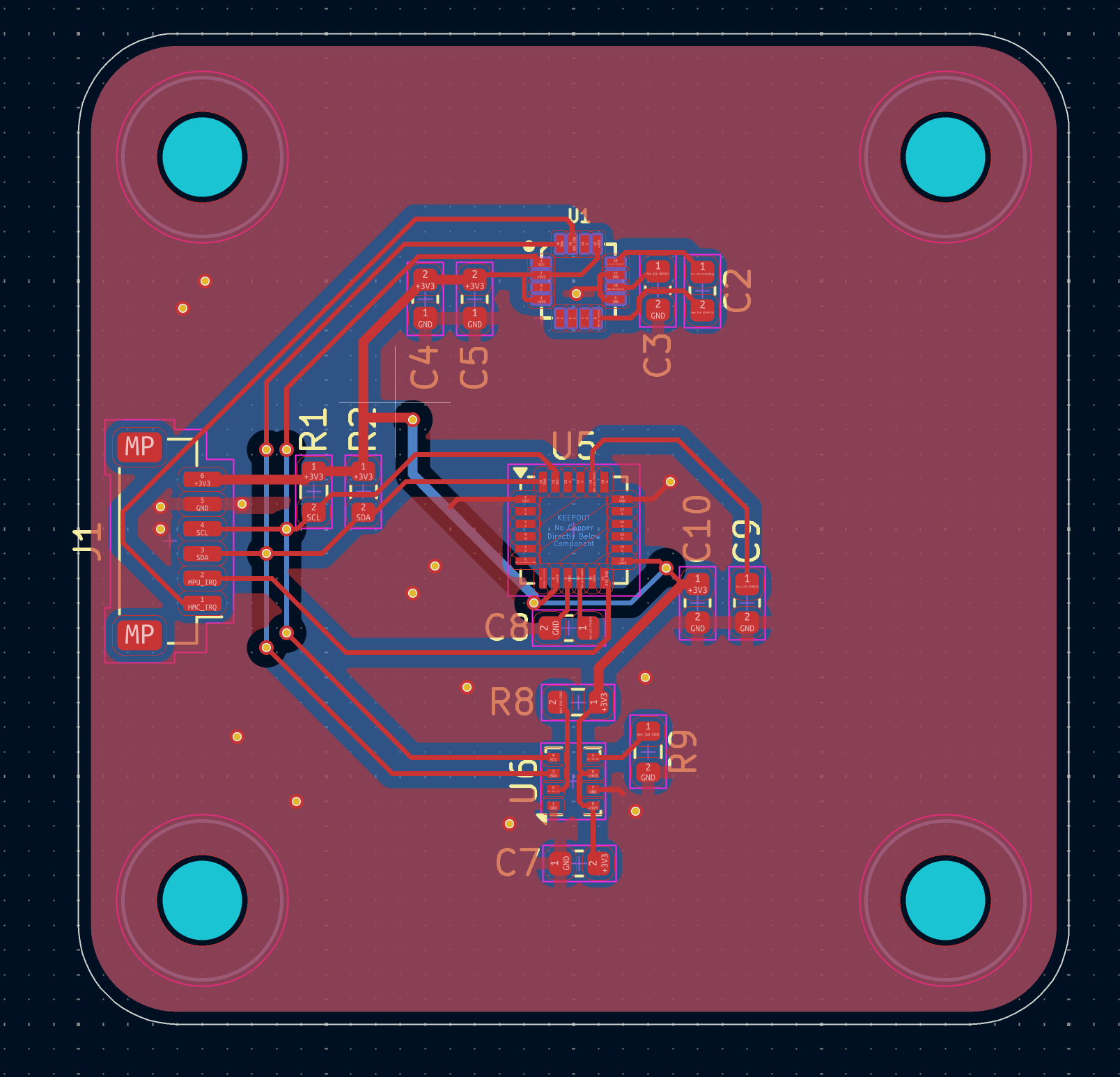
SkyIMU is an open-source printed circuit board by rmingon, from the rmingon/SkyIMU repository on GitHub. It is a 2-layer board of 40 × 40 mm with 20 parts on 31 nets, routed with 128 tracks and 24 vias.
It is built around the BMP280, HMC5883L and MPU-6050. Its parts include 8 capacitors, 4 resistors, 3 ICs and 1 connector. It belongs with the sensors and measurement boards of this library.


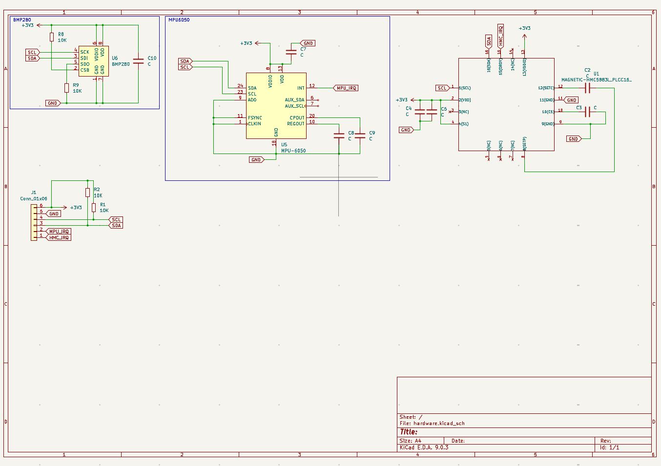
Compact 3.3 V sensor board that combines an InvenSense MPU-6050 6-axis IMU, a Honeywell HMC5883L 3-axis magnetometer, and a Bosch BMP280 barometric pressure and temperature sensor. All sensors share a single I2C bus exposed on a JST-SH connector alongside dedicated interrupt outputs, giving a small-footprint attitude and environment module that drops into embedded builds.
SCL/SDA.CSB pulled high, SDO low -> address 0x76); MPU-6050 address fixed at 0x68.MPU_IRQ, HMC_IRQ) on the main connector for low-latency data-ready signaling.Power
Pin 6 of J1.Pin 5 of J1 ties to the common ground plane.I2C Bus
SCL (Pin 4) and SDA (Pin 3) are pulled up to 3.3 V with 10 kOhm (R1, R2).Interrupts
MPU_IRQ (Pin 2) exposes the MPU-6050 INT pin (active-high).HMC_IRQ (Pin 1) exposes the HMC5883L DRDY pin (active-high).I2C Addresses
AD0 tied low): 0x680x1ESDO pulled low): 0x76| Pin | Signal | Direction | Notes |
|---|---|---|---|
| 1 | HMC_IRQ | Output | HMC5883L data-ready (interrupt capable). |
| 2 | MPU_IRQ | Output | MPU-6050 INT line. |
| 3 | SDA | I/O | I2C data, pulled up to 3.3 V. |
| 4 | SCL | Output | I2C clock, pulled up to 3.3 V. |
| 5 | GND | Power | Common ground. |
| 6 | +3V3 | Power | 3.3 V input. |
Pin numbering follows the JST silkscreen indicator (Pin 1 nearest the notch). Ensure the mating cable respects the reversed numbering typical of JST-SH harnesses.
hardware/ - KiCad 9 project (hardware.kicad_pro, .kicad_sch, .kicad_pcb) plus footprint cache.schematic.png - Quick schematic preview.pcb.png - Rendered PCB top view.Open the design in KiCad 9 or newer. To generate fabrication outputs, use kicad-cli pcb export gerbers / kicad-cli pcb export drill or the KiCad plot dialog.
SDA/SCL to an I2C peripheral.MPU_IRQ / HMC_IRQ to interrupt-capable GPIOs.
LICENSE for details.| Qty | Value | Footprint | References |
|---|---|---|---|
| 8 | C | Capacitor_SMD:C_0603_1608Metric | C2, C3, C4, C5, C7, C8, C9, C10 |
| 4 | 10K | Resistor_SMD:R_0603_1608Metric | R1, R2, R8, R9 |
| 1 | BMP280 | Package_LGA:Bosch_LGA-8_2x2.5mm_P0.65mm_ClockwisePinNumbering | U6 |
| 1 | Conn_01x06 | Connector_JST:JST_SH_BM06B-SRSS-TB_1x06-1MP_P1.00mm_Vertical | J1 |
| 1 | MAGNETIC-HMC5883L_PLCC16_ | MAGNETIC-HMC5883L_PLCC16_:PLCC16-0.5-3X3MM | U1 |
| 1 | MPU-6050 | Sensor_Motion:InvenSense_QFN-24_4x4mm_P0.5mm | U5 |
The 16 most common of 20 parts.


Kmshanley/MiniRobots
Firmware and PCB desgin for mini robots with UWB localization and lidar mapping

phonght32/OpenDrone_HW_FC_F405
OpenDrone Project - Fly Controller hardware using STM32F405RG.


Eryk-Mozdzen/hogger2
Hemispherical Omnidirectional Gimbaled (HOG) wheel - this robot have two of them


zenitheesc/Zenith-Development-Board
The Zenith Development Board was developed to serve as a first project for the new members of the group.
It measures 40 × 40 mm and has 2 copper layers, 1.6 mm thick.
20 parts, built around the BMP280, HMC5883L and MPU-6050. The full list of its parts is on this page, with links to each part's symbol and footprint where PCBKit's library has them.
From the rmingon/SkyIMU repository on GitHub, at the commit this page was made from: the board is hardware/hardware.kicad_pcb and its schematic hardware/hardware.kicad_sch. PCBKit opens the board in the browser, with nothing to install.
Its repository states no licence, so its author keeps all rights: ask rmingon before reusing the design.