
2 layers50.8 × 50.8 mm

 rmingon/drone-uwb13
Drone design for automatic position in space with UWB
Drone is an open-source printed circuit board by rmingon, from the rmingon/drone-uwb repository on GitHub. It is a 2-layer board of 115 × 115 mm with 49 parts on 88 nets, routed with 456 tracks and 103 vias.
It is built around the CH340C, DWM1000 and ESP32-WROOM-32, with the BMP280, LM1117MP-3.3 and MPU-6050 among its other parts. Its parts include 16 resistors, 9 capacitors, 6 ICs, 6 diodes and 6 transistors. It belongs with the robots and motor control boards and the ESP32 boards of this library.


A quadcopter that knows where it is, to the centimetre, without GPS.
Ultra wide band anchors on the ground, a tag on the drone, and time of flight ranging between them.




GPS stops at the door and drifts by metres. Ultra wide band does not: a DW1000 timestamps a radio pulse to 15.65 picoseconds, which is 4.7 mm of flight time. Measure the round trip between two radios and you get a distance, not a guess from signal strength.
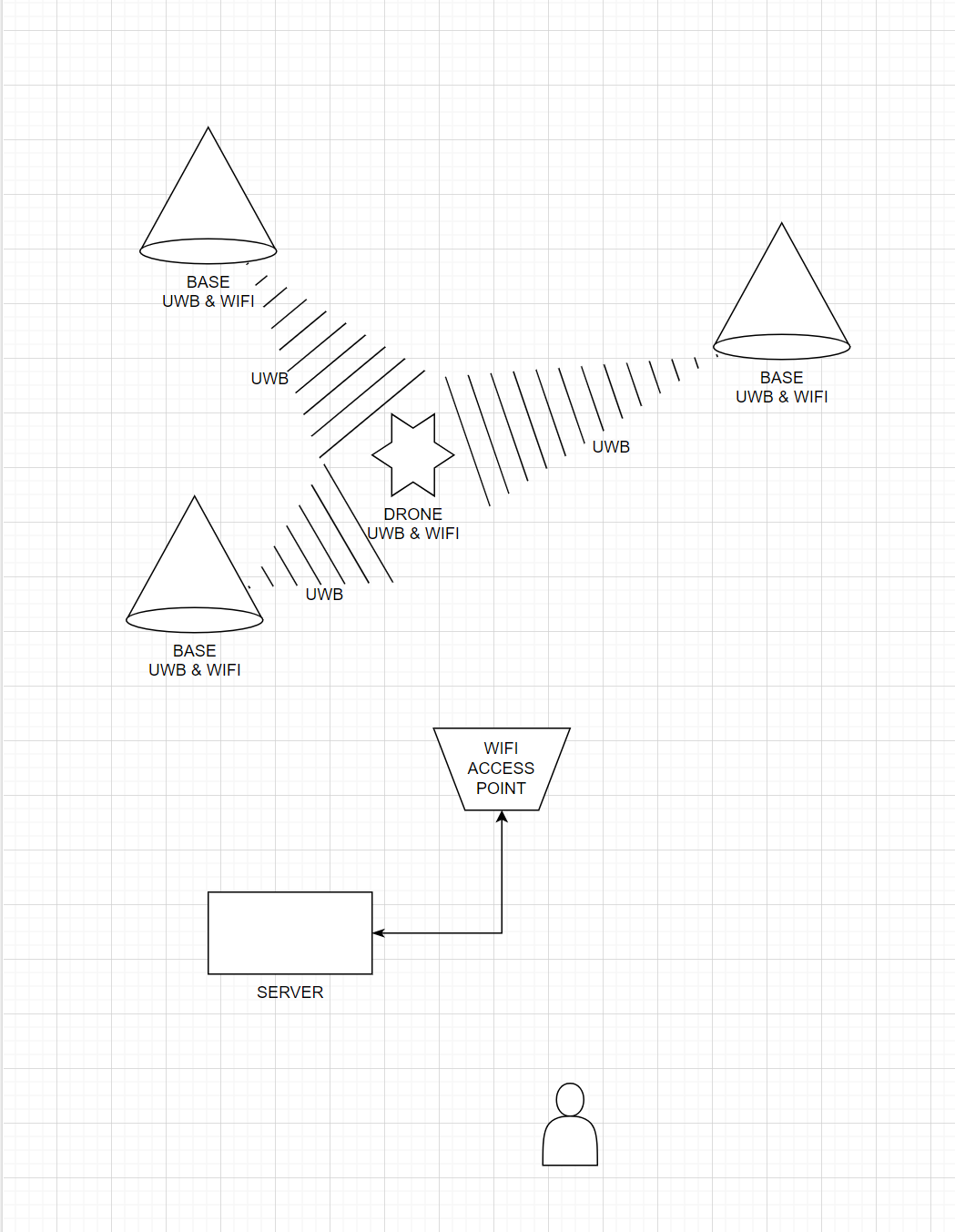
Anchors are chained. A tag walks the whole chain on every cycle and comes out with one distance per anchor:
   drone (tag)                anchors
        |
        |  blink  ------------------------------->  main anchor
        |  <---------------  short address  ------  main anchor
        |                                             |
        |  <====  two way ranging  ====>  anchor 1     | measures, reports
        |  <====  two way ranging  ====>  anchor 2     | measures, reports
        |  <====  two way ranging  ====>  anchor 3     | measures, reports
        |                                             |
        |  <-------------  back to blinking  -------  last anchor
Every anchor computes its own distance and pushes it to the server over UDP. Three clear distances are enough to place the drone on a plane, four to place it in space.
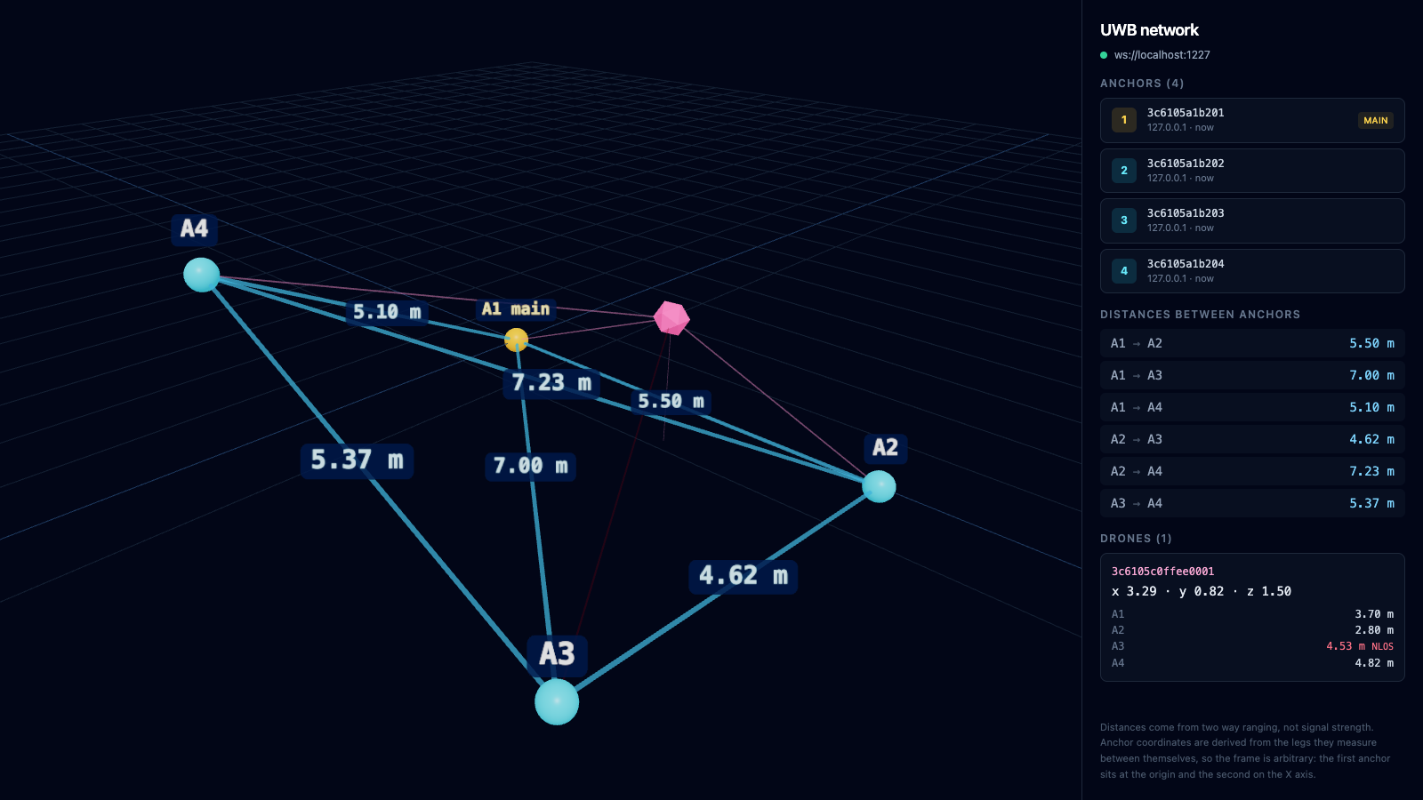
Between tag cycles, each anchor plays tag towards its peers. That gives the distance matrix of the installation itself, and the server turns it into coordinates, so nobody has to measure a room with a tape:
   anchor 1 ---- 5.50 m ---- anchor 2        first anchor  -> origin
      |  \                    /  |           second       -> on the X axis
   5.10   7.00          4.62    7.23         third        -> in the XY plane
      |        \      /         |            the rest     -> trilaterated
   anchor 4 ---- 5.37 m ---- anchor 3
Distances alone cannot tell a layout from its mirror image, so the convention above is part of the answer rather than a measurement.
| Time of flight | The distance comes from an asymmetric two way ranging exchange, not from RSSI. Typical accuracy is around 10 cm once calibrated. |
| Bias correction | The APS011 range bias table is applied to every measurement, worth 10 to 20 cm at short range. |
| Median filter | Each anchor reports the median of its last 5 exchanges, so a single multipath reflection cannot move the result. |
| Line of sight check | A measurement whose first path power sits more than 6 dB below the total receive power is flagged, and the server keeps it out of the position fix. |
| Antenna delay calibration | Stored per board in NVS and pushed over the network, see below. |
| Path | What it is |
|---|---|
base/code | Anchor firmware, ESP-IDF. Runs the ranging chain and reports distances. |
base/ | Anchor board, with and without battery (KiCad) |
code/drone | Drone firmware, Arduino. Flight control, plus the UWB tag on its own task. |
code/server | Bun server. Collects distances, solves the layout and the drone positions. |
code/front | Web interface, Vue and TresJS 3D view |
drone_with_esc | Drone board with 30 A ESCs (KiCad) |
drone | Drone board with integrated drivers (KiCad) |
drone_2s | Drone board for a 2S battery (KiCad) |
Flash one board per anchor, each with its own address. One of them, and only one, is the main anchor.
cd base/code
$EDITOR src/config.h     # wifi, server, ANCHOR_ADDRESS, ANCHOR_IS_MAIN
pio run -t upload
pio device monitor
The chain is described entirely in src/config.h. The last anchor sets
ANCHOR_NEXT_ADDRESS to 0, which sends the tag back to blinking:
// anchor 1              anchor 2              anchor 3 (last)
ANCHOR_ADDRESS      1    ANCHOR_ADDRESS      2    ANCHOR_ADDRESS      3
ANCHOR_IS_MAIN      1    ANCHOR_IS_MAIN      0    ANCHOR_IS_MAIN      0
ANCHOR_NEXT_ADDRESS 2 ANCHOR_NEXT_ADDRESS 3 ANCHOR_NEXT_ADDRESS 0cd code/drone
$EDITOR src/config.h # wifi, websocket endpoint
pio run -t uploadcd code/server && bun install && bun run src/index.ts
cd code/front && bun install && bun run devThe interface shows the anchors, the distances they measure between themselves
and the drones, in 3D. With no hardware running, open it with ?demo=1 to see
it against generated data.
Both ends of every link have to agree on every radio setting, so the profile
lives in a single file that is kept identical in
base/code/src/uwb_profile.h and
code/drone/src/uwb_profile.h.
| long range (default) | fast | |
|---|---|---|
| Data rate | 110 kbps | 850 kbps |
| Preamble | 2048 symbols | 256 symbols |
| Pulse frequency | 64 MHz | 16 MHz |
| SFD | Decawave (non standard) | standard |
| Preamble code | 9 | 3 |
| Frame airtime | about 4 ms | about 0.5 ms |
| Link budget | about 6 dB better | baseline |
| Usable range | roughly 2x | baseline |
| Air time per cycle | roughly 8x more | baseline |
Switch by flipping UWB_PROFILE_LONG_RANGE and UWB_PROFILE_FAST in that
header, on every board. The channel (5) is the same on both, so the two profiles
share the same spectrum, just not the same air time.
Changing profile invalidates the antenna delay. It depends on the pulse frequency, so a board calibrated at 16 MHz is not calibrated at 64 MHz. The anchors store the value under a per profile key so the two calibrations never get mixed up, but each one still has to be measured.
Antenna delay is the single largest source of constant error. One unit is about 4.7 mm, so a board left on the generic 16436 is easily half a metre off, and no amount of filtering will fix a constant offset.
echo -n '{"antenna_delay": 16450}' | nc -u -w1 <anchor ip> 7051DW1000_ANTENNA_DELAY in src/config.h is only the fallback for a board that
has never been calibrated.
Calibration and filtering only go so far; the antenna installation does the rest.
Anchors talk to the server over UDP on port 7051, in both directions.
Anchor to server, wrapped in {"uniq": "<anchor mac>", "type": ..., "data": {...}}:
| type | data | when |
|---|---|---|
anchor | {"address": 1, "main": true} | at boot |
tag | {"eui": "aabbccddeeff0001", "address": 5} | main anchor, when it hands a short address to a tag |
range | {"address": 5, "range": 3.42, "raw_range": 3.51, "rx_power": -82.3, "fp_power": -85.1, "los": true} | every completed exchange with a tag |
peer | same shape, address being another anchor | every completed exchange with a peer anchor |
Server to anchor:
| payload | effect |
|---|---|
{"reboot": true} | restarts the board |
{"antenna_delay": 16450} | stores a calibration in NVS and applies it |
A secondary anchor only ever sees the short address the main anchor handed out, which is why the main anchor publishes the address to EUI mapping. The drone announces the same EUI when it connects, and that is what ties a distance back to a drone.
| Anchor firmware, ESP-IDF | builds, not yet flown |
| Two way ranging, both ends | builds, awaiting bench validation |
| Anchor self survey | builds, not yet flown |
| Distance collection on the server | working, covered by tests |
| Anchor layout and drone position | working, covered by tests |
| Web interface | working, 3D view of anchors, distances and drones |
| Autonomous flight | the goal |
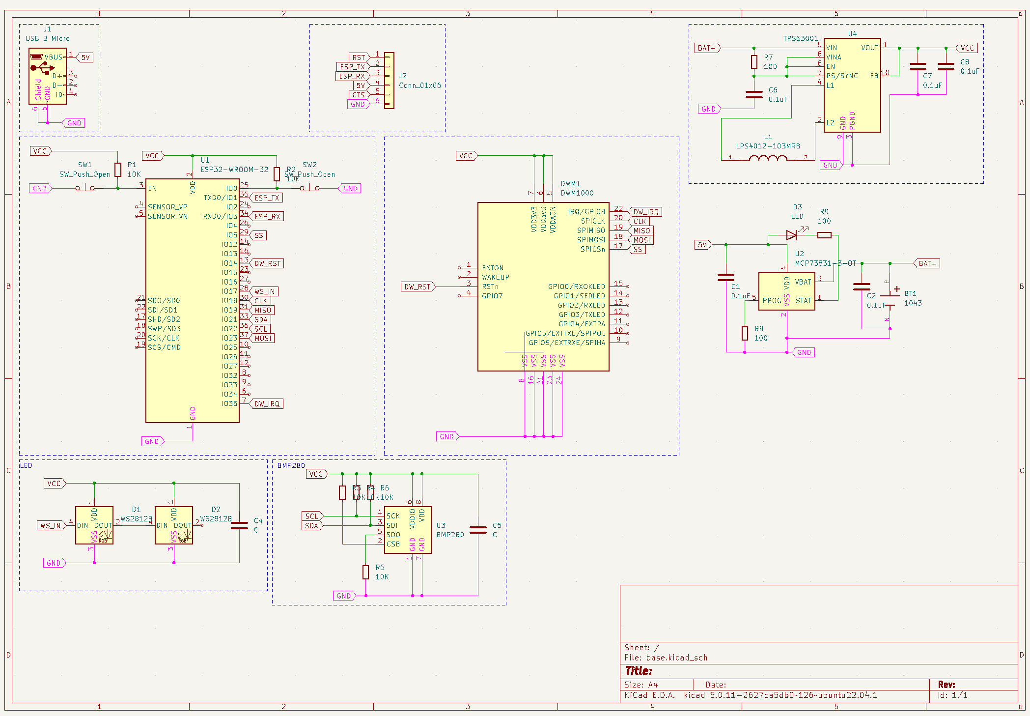
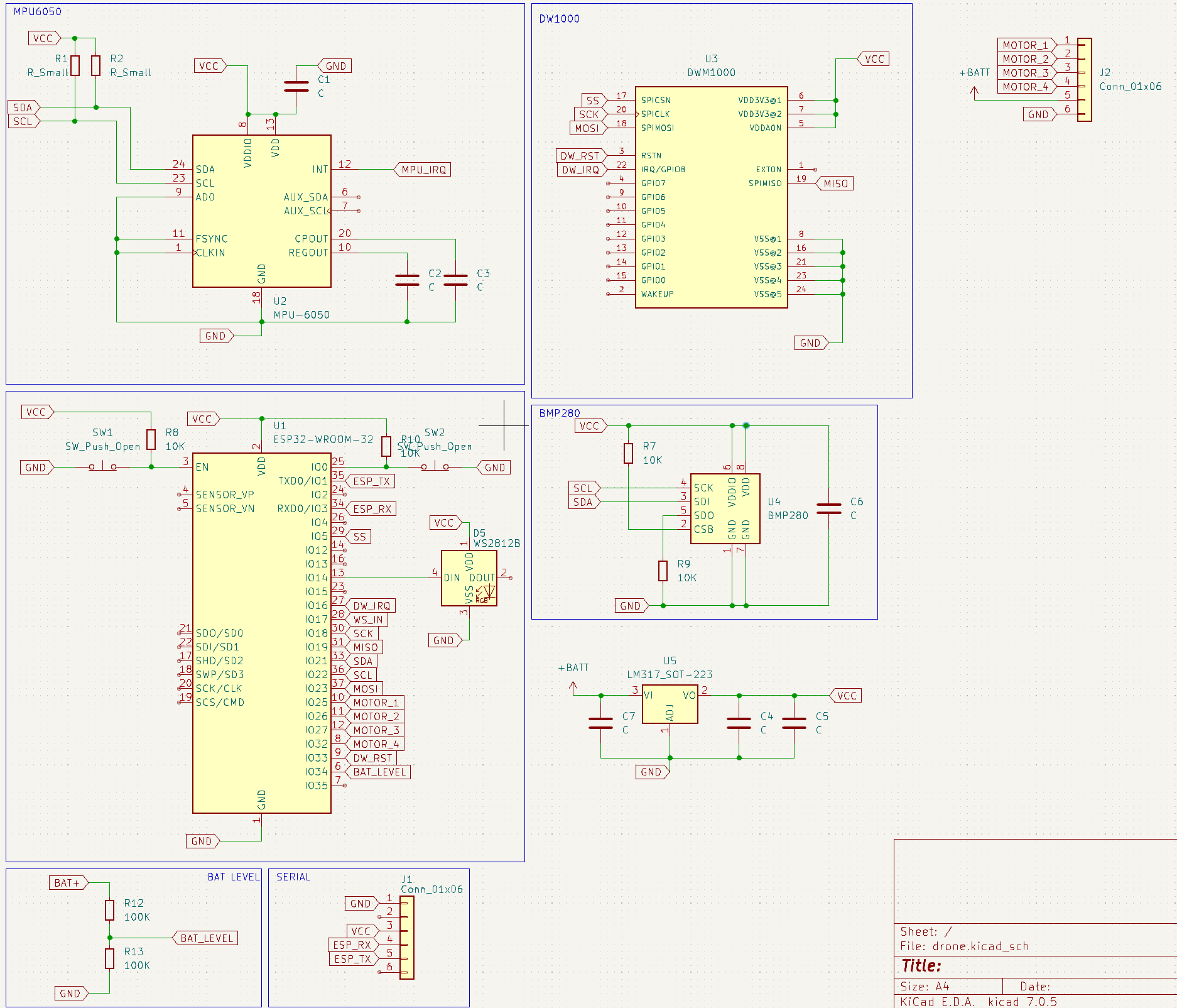
Schematic
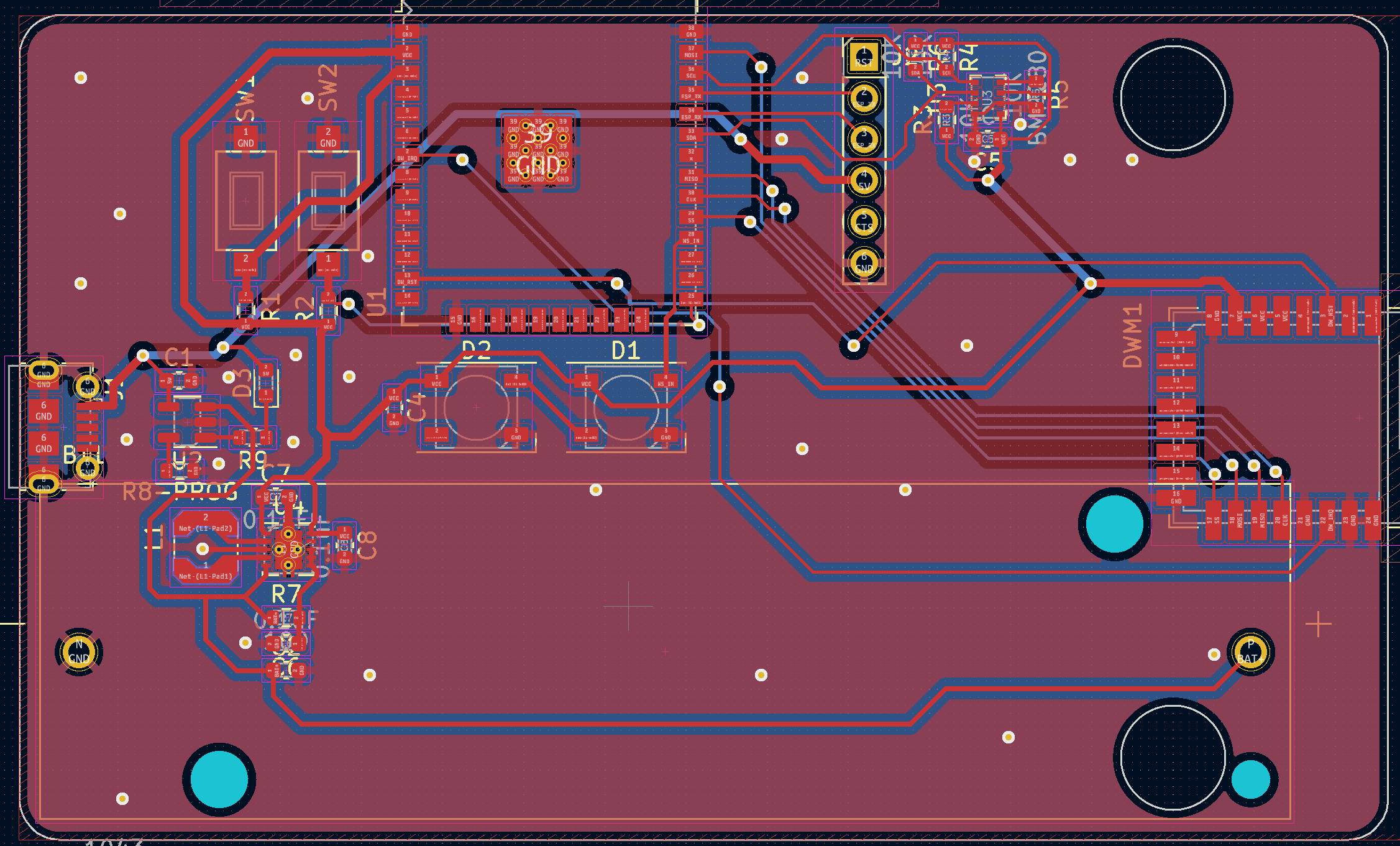
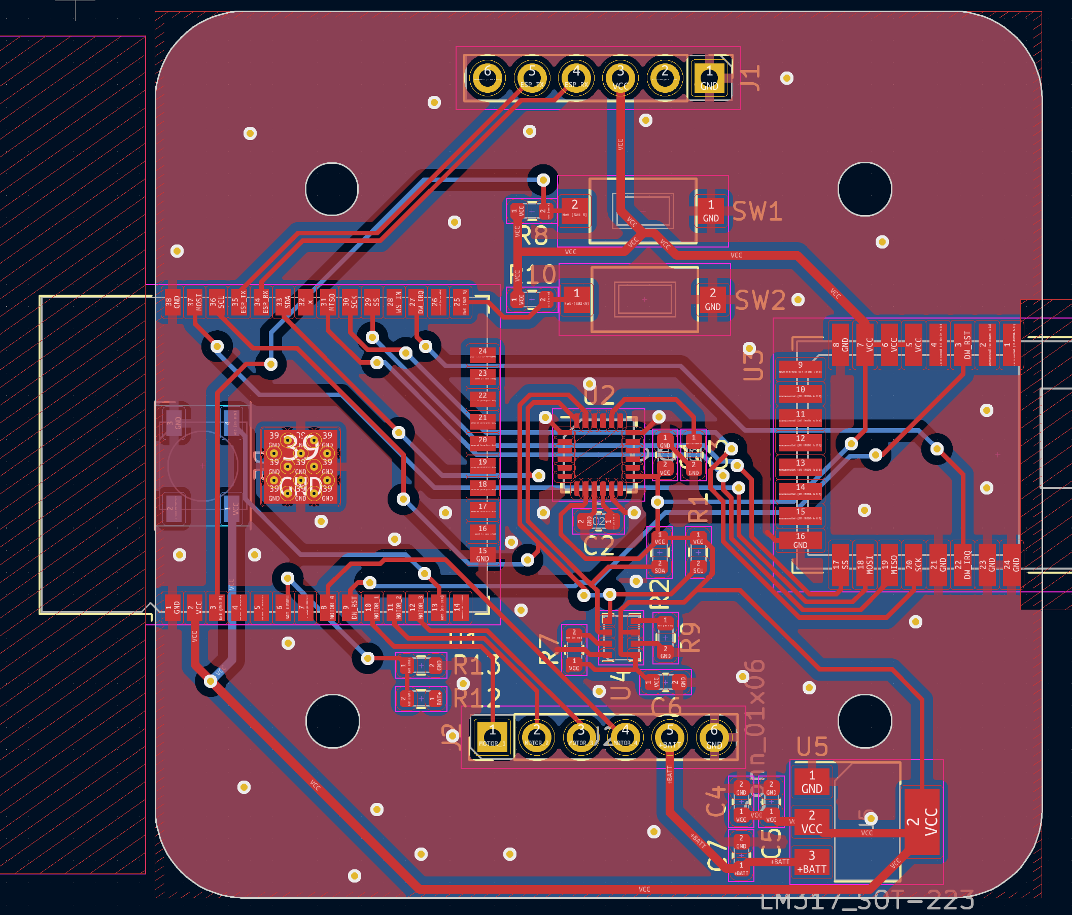
PCB
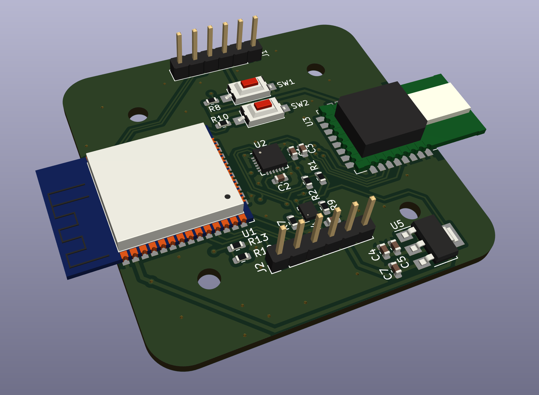
3D
Schematic
PCB
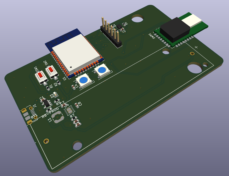
3D
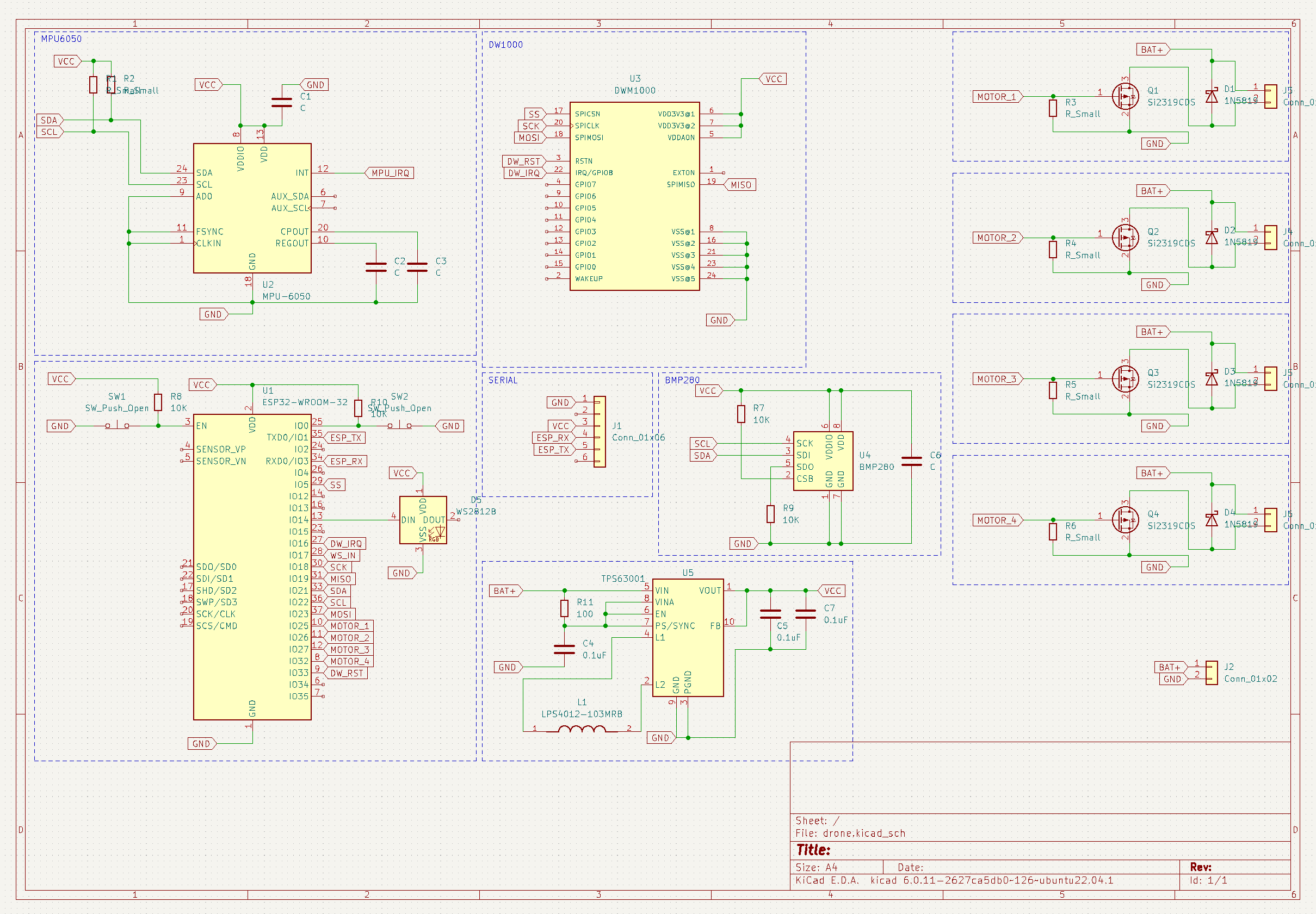
Schematic
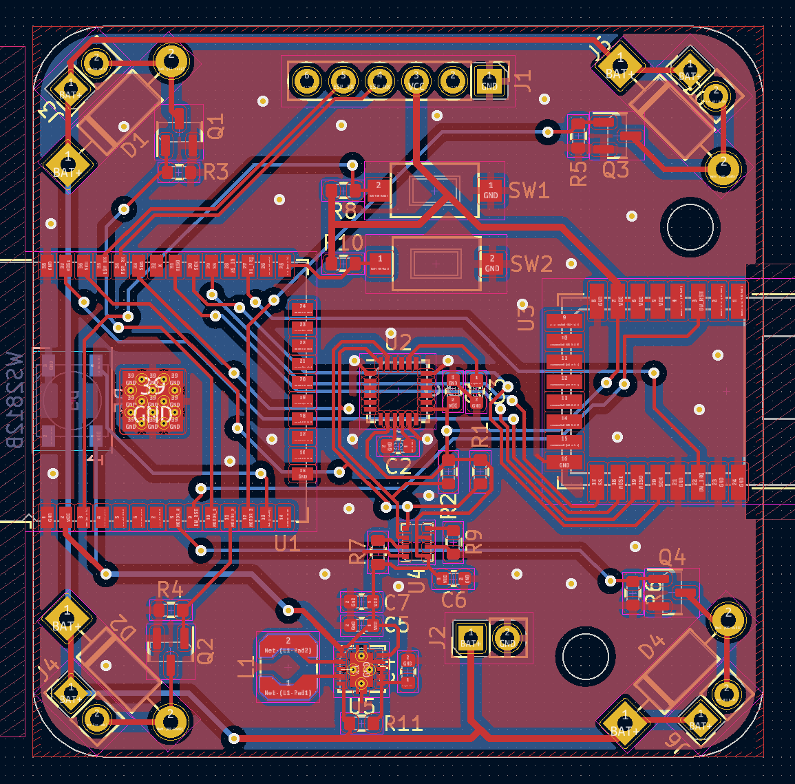
PCB
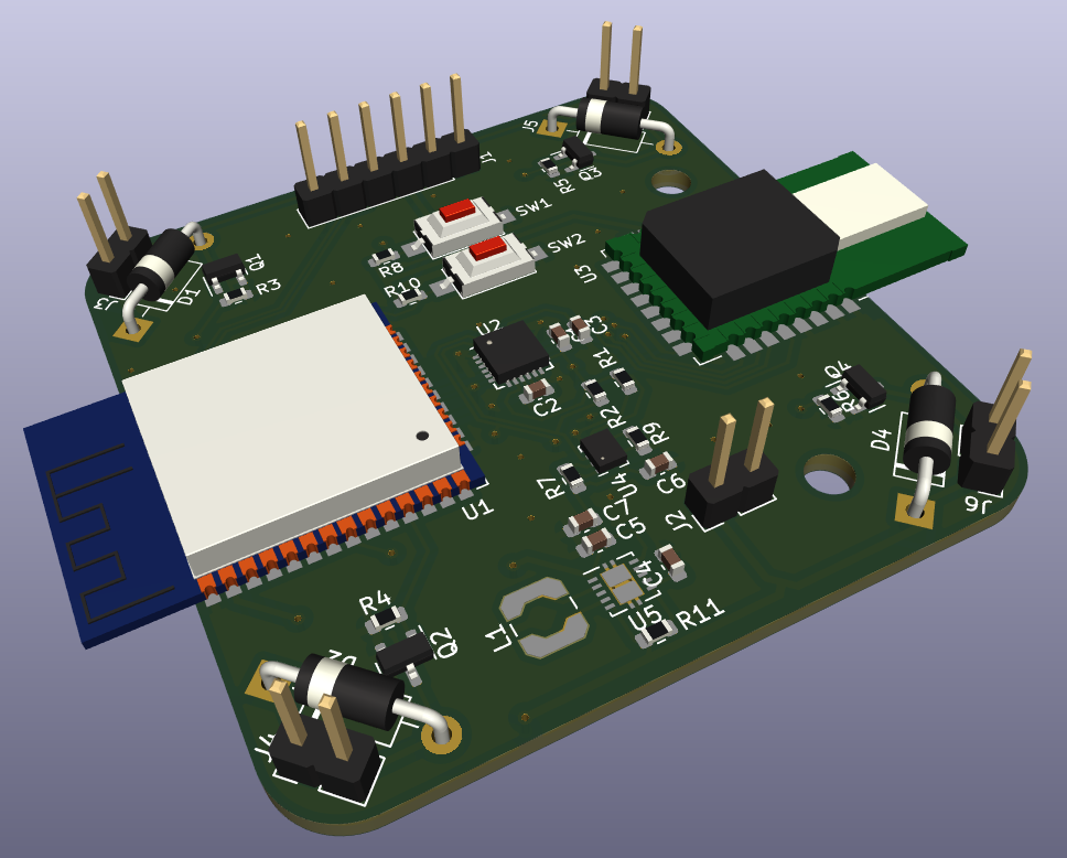
3D
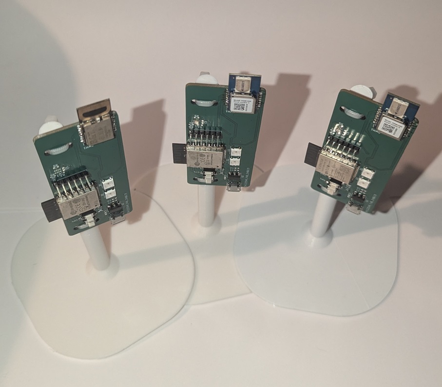
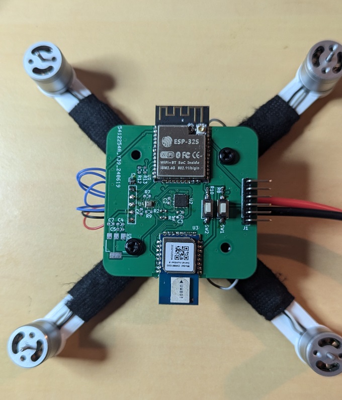
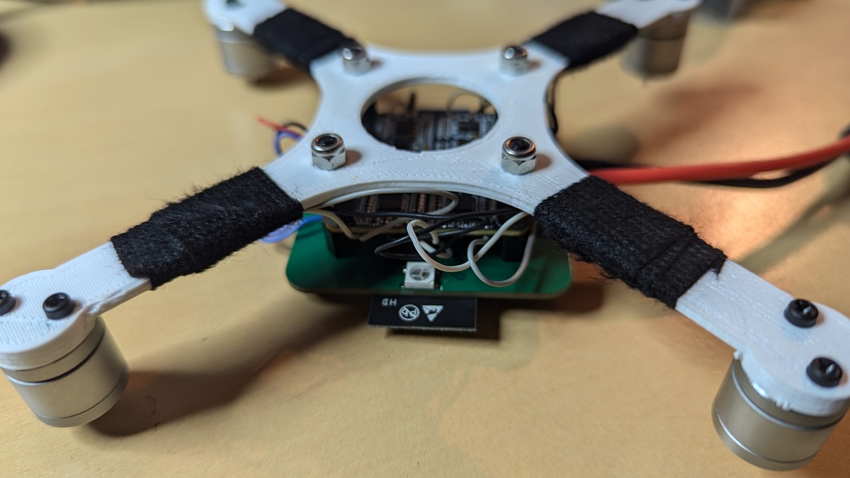
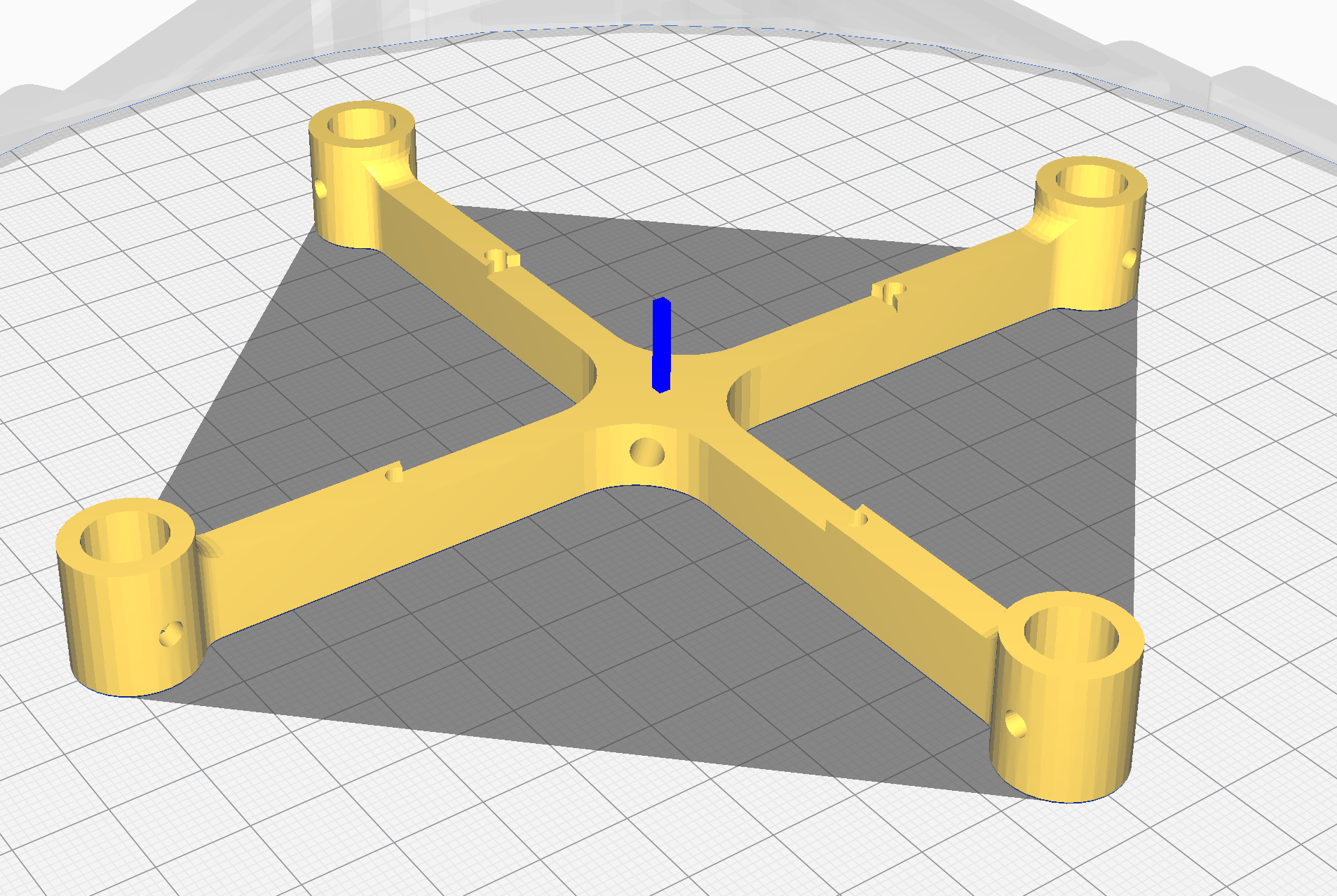
Real board
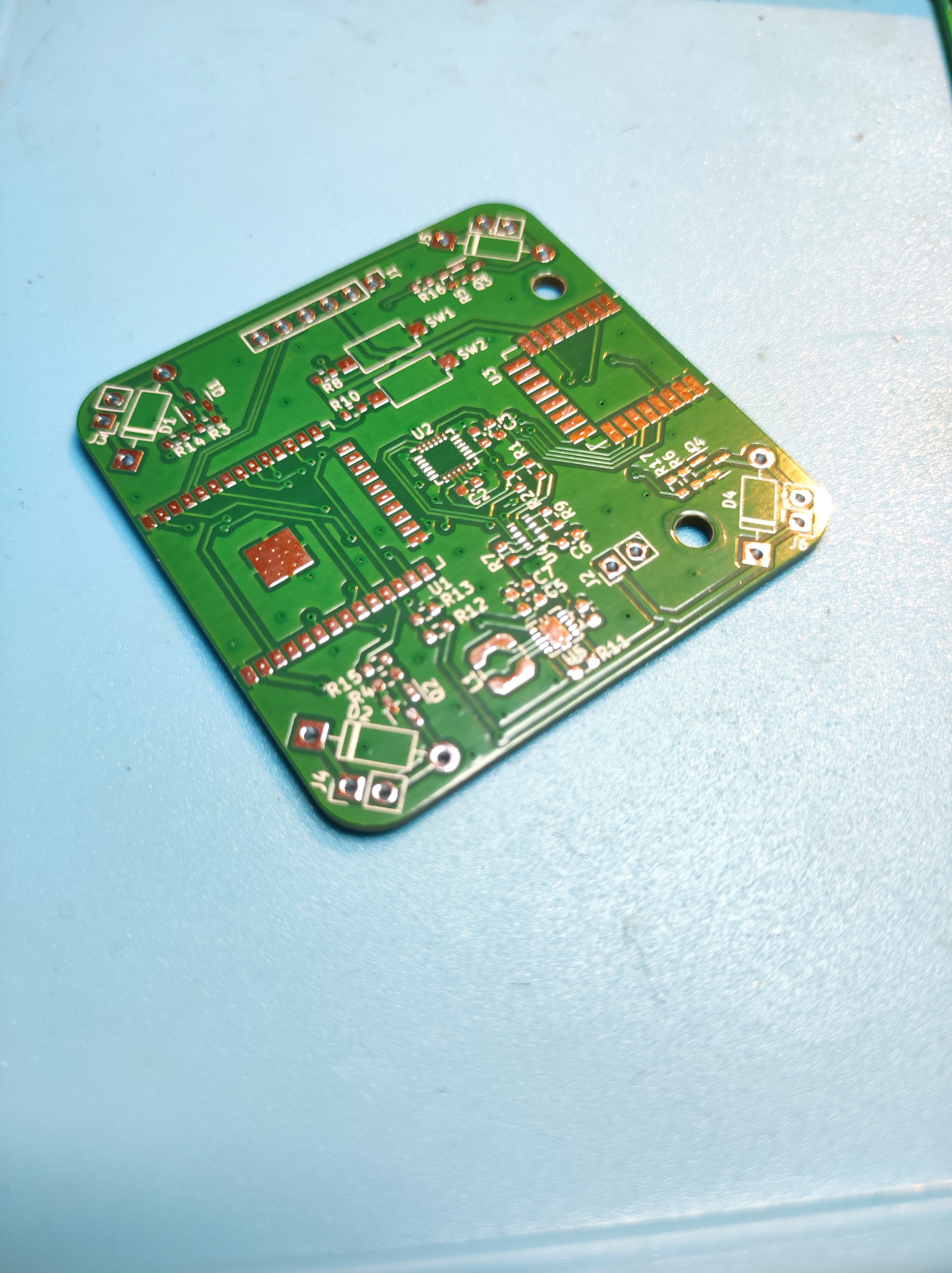
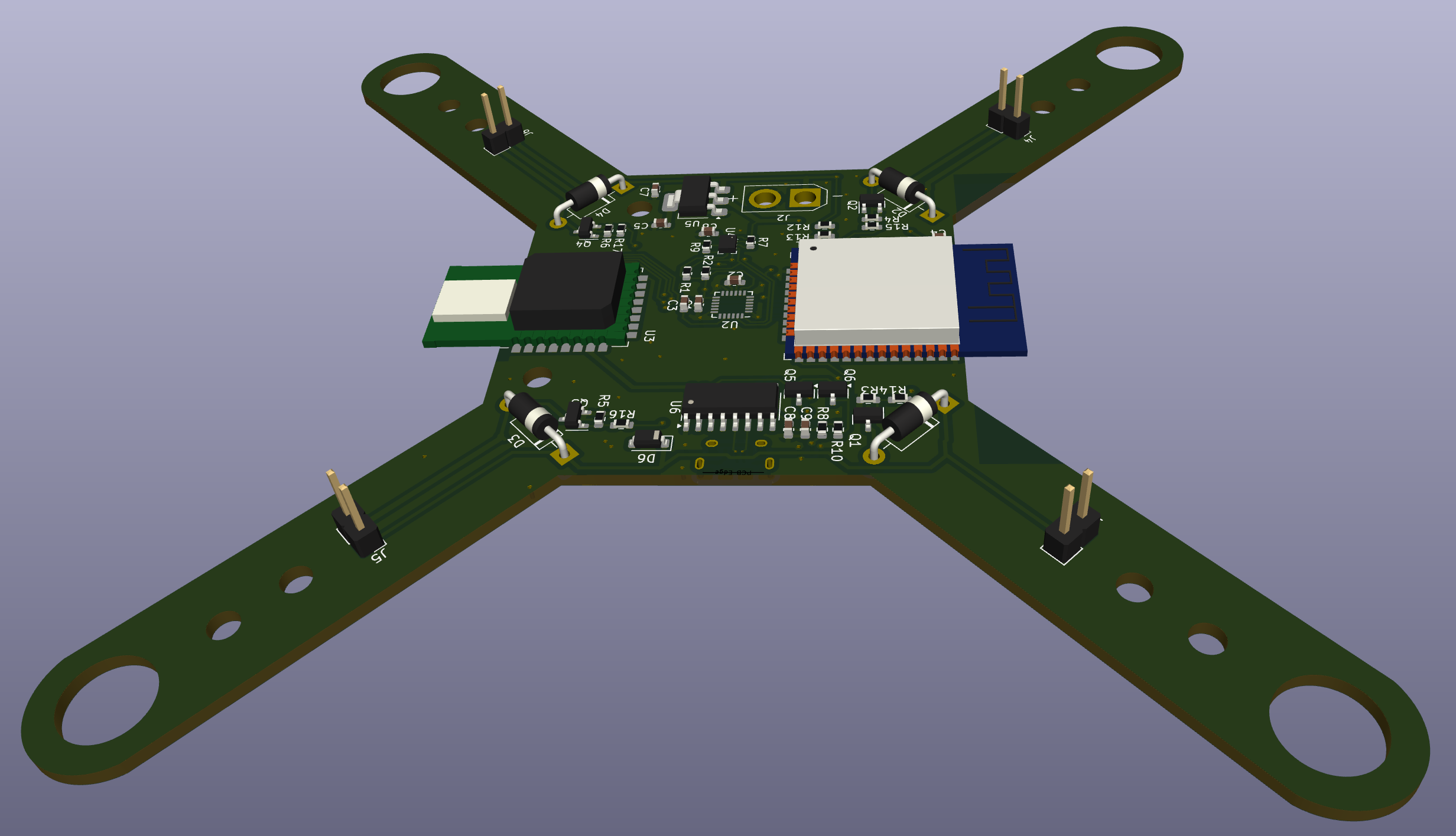
Thank you to PCBWay for sponsoring the PCB production of this prototype. The boards turned out very nicely: the green solder mask looks solid and the grill holes are perfect.
The DW1000 driver is a port of
F-Army/arduino-dw1000-ng (MIT),
vendored in base/code/components/DW1000Ng.
| Qty | Value | Footprint | References |
|---|---|---|---|
| 10 | R_Small | Resistor_SMD:R_0603_1608Metric | R1, R2, R3, R4, R5, R6, R14, R15, R16, R17 |
| 9 | C | Capacitor_SMD:C_0603_1608Metric | C1, C2, C3, C4, C5, C6, C7, C8, C9 |
| 4 | 10K | Resistor_SMD:R_0603_1608Metric | R7, R8, R9, R10 |
| 4 | 1N5819 | Diode_THT:D_DO-41_SOD81_P10.16mm_Horizontal | D1, D2, D3, D4 |
| 4 | Conn_01x02 | Connector_PinHeader_2.54mm:PinHeader_1x02_P2.54mm_Vertical | J3, J4, J5, J6 |
| 4 | Si2319CDS | Package_TO_SOT_SMD:SOT-23 | Q1, Q2, Q3, Q4 |
| 2 | 100K | Resistor_SMD:R_0603_1608Metric | R12, R13 |
| 2 | BSS138 | Package_TO_SOT_SMD:SOT-23 | Q5, Q6 |
| 1 | 1N4148W | Diode_SMD:D_SOD-123 | D6 |
| 1 | BMP280 | Package_LGA:Bosch_LGA-8_2x2.5mm_P0.65mm_ClockwisePinNumbering | U4 |
| 1 | CH340C | Package_SO:SOIC-16_3.9x9.9mm_P1.27mm | U6 |
| 1 | Conn_01x02 | Connector_AMASS:AMASS_XT30U-F_1x02_P5.0mm_Vertical | J2 |
| 1 | DWM1000 | RF_Module:DWM1000 | U3 |
| 1 | ESP32-WROOM-32 | RF_Module:ESP32-WROOM-32 | U1 |
| 1 | LM1117MP-3.3 | Package_TO_SOT_SMD:SOT-223-3_TabPin2 | U5 |
| 1 | MPU-6050 | Sensor_Motion:InvenSense_QFN-24_4x4mm_P0.5mm | U2 |
| 1 | USB_B_Micro | Connector_USB:USB_Micro-B_Amphenol_10118194_Horizontal | J7 |
| 1 | WS2812B | LED_SMD:LED_WS2812B_PLCC4_5.0x5.0mm_P3.2mm | D5 |


rmingon/Falcon-Edge
A 3D-printable flying-wing airframe with a custom ESP32 flight computer—open hardware you can solder, screw together, and fly.


Kmshanley/MiniRobots
Firmware and PCB desgin for mini robots with UWB localization and lidar mapping


FrancoStrappazzon/Drones
Repositorio para proyectos de drones, desde el más simple hasta mas complejos

It measures 115 × 115 mm and has 2 copper layers, 1.6 mm thick.
49 parts, built around the CH340C, DWM1000, ESP32-WROOM-32 and BMP280. The full list of its parts is on this page, with links to each part's symbol and footprint where PCBKit's library has them.
From the rmingon/drone-uwb repository on GitHub, at the commit this page was made from: the board is drone_2s/drone.kicad_pcb and its schematic base/base_with_battery/base.kicad_sch. PCBKit opens the board in the browser, with nothing to install.
Its repository states no licence, so its author keeps all rights: ask rmingon before reusing the design.