4 layers17.8 × 41.9 mm

 red-scorp/RP2040-ProMini8
RP2040-based board with footprint of Arduino ProMini
RP2040-ProMini is an open-source printed circuit board by red-scorp, from the red-scorp/RP2040-ProMini repository on GitHub. It is a 4-layer board of 17.8 × 41.9 mm with 44 parts on 63 nets, routed with 728 tracks and 141 vias.
It is built around the RP2040, W25Q128JVEIQ and W25Q128JVSIQ, with the TPS63060DSC and AO3400A among its other parts. Its parts include 15 capacitors, 9 resistors, 7 connectors, 4 ICs and 2 diodes. It belongs with the RP2040 and AVR (ATmega, ATtiny) boards of this library.


 ______  ______ ______   ______   __     ______     ______           ______  _       _
(_____ \(_____ (_____ \ / __   | / /    / __   |   (_____ \         |  ___ \(_)     (_)
 _____) )_____) )____) ) | //| |/ /____| | //| |___ _____) )___ ___ | | _ | |_ ____  _
(_____ (|  ____//_____/| |// | |___   _) |// | (___)  ____/ ___) _ \| || || | |  _ \| |
      | | |     _______|  /__| |   | | |  /__| |   | |   | |  | |_| | || || | | | | | |
|_|_| (_______)\_____/ |_| \_____/ |_| |_| \___/|_||_||_|_|_| |_|_|The RP2040-ProMini project aims to create a replacement for the Arduino Pro Mini using the RP2040 MCU.
The RP2040-ProMini board is a 4-layer board designed to accommodate the popular Raspberry Pi RP2040 MCU in the commonly used, but obsolete, Arduino Pro Mini footprint.
Preview:
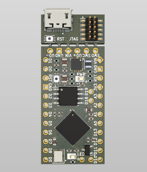
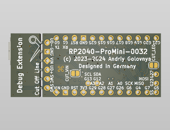
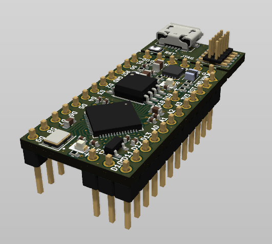
You can view the Schematics in PDF format for detailed information.
STEP 3D files are available with pins and without pins.
Features:
CAM files, as well as the BOM and CPL files for JLCPCB, are available.
Following pinout is used for the board:
| Board Pin | RP2040 Pin | Function | Notes |
|---|---|---|---|
| D0 | GPIO1 | UART0 TX | |
| D1 | GPIO0 | UART0 RX | |
| D2 | GPIO25 | ||
| D3 | GPIO15 | ||
| D4 | GPIO16 | ||
| D5 | GPIO17 | ||
| D6 | GPIO18 | ||
| D7 | GPIO19 | ||
| D8 | GPIO20 | ||
| D9 | GPIO21 | ||
| D10 | GPIO5 | SS | |
| D11 | GPIO7 | MOSI | |
| D12 | GPIO4 | MISO | |
| D13 | GPIO6 | SCK | LED |
| D14 A0 | GPIO26 | ||
| D15 A1 | GPIO27 | ||
| D16 A2 | GPIO28 | ||
| D17 A3 | GPIO29 | ||
| D18 | GPIO12 | SDA | |
| D19 | GPIO13 | SCL | |
| D20 | GPIO22 | ||
| D21 | GPIO23 |
There are two cut points on the board to reduce power consumption of unused components.
| Cut Point | Function | Notes |
|---|---|---|
| CUT_VIN | Separates VIN-to-3V3 power supply with power LED from the rest of the board | This cut point is useful if you want to power the board from 3V3 pin instead of VIN pin. |
| CUT_LED | Separates LED on pin D13 from the rest of the board | This cut point is useful if you want to reduce power consumption of the board. |
Roughly RP2040-ProMini board exists in three flavors:
The development of v3.x boards is happening in master branch, while v1.x and v2.x boards are developed in dev_v1 and dev_v2 branches respectively.
Each board version listed below is tagged in its respective branch and includes all the necessary files to manufacture the board.
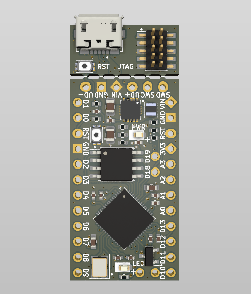
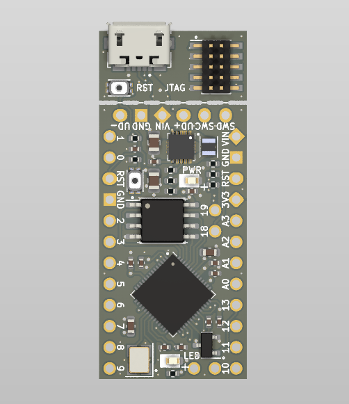
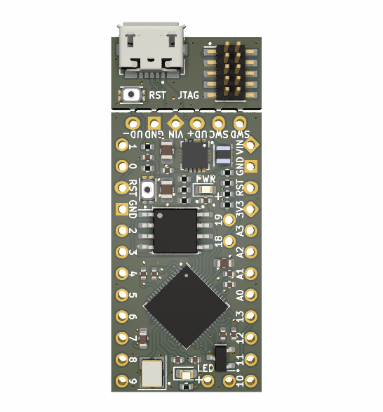
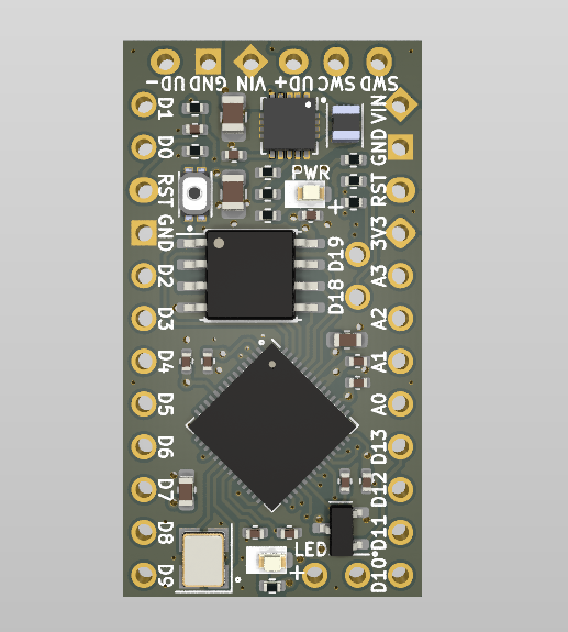
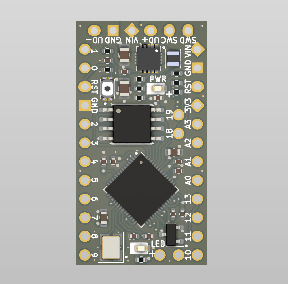
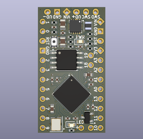
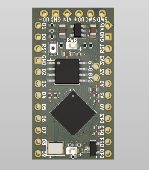
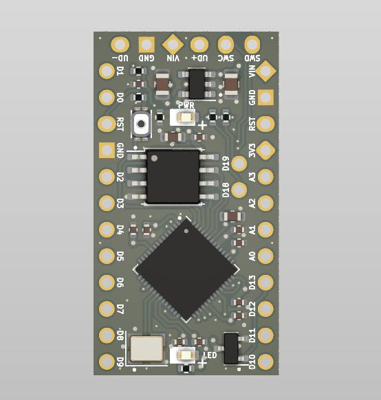
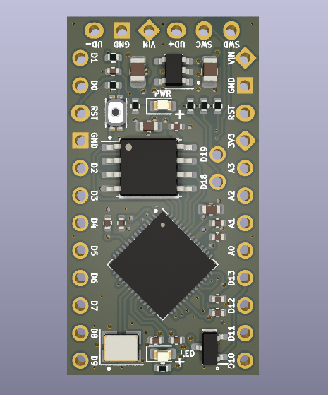
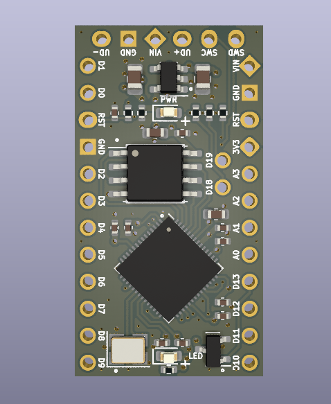
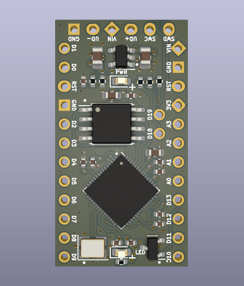
Initial release for testing purposes.
Your contributions as code, resources, or finances are welcome! Please contact me directly via email at andriy.golovnya@gmail.com or through my GitHub profile.
If you'd like to make a financial contribution, you can donate via PayPal or Ko-Fi. Your support is greatly appreciated.
Thanks in advance!
| Qty | Value | Footprint | References |
|---|---|---|---|
| 11 | 100nF | Capacitor_SMD:C_0402_1005Metric | C2, C3, C4, C6, C7, C8, C9, C10, C11, C13, C15 |
| 3 | 10k | Resistor_SMD:R_0402_1005Metric | R3, R4, R5 |
| 2 | 10uF | Capacitor_SMD:C_0805_2012Metric | C12, C14 |
| 2 | 1M | Resistor_SMD:R_0402_1005Metric | R8, R9 |
| 2 | 2.2uF | Capacitor_SMD:C_0603_1608Metric | C1, C5 |
| 2 | 5k1 | Resistor_SMD:R_0402_1005Metric | R1, R6 |
| 2 | RED | LED_SMD:LED_0603_1608Metric | D1, D2 |
| 1 | 1.5uH | Inductor_SMD:L_Murata_DFE201610P | L1 |
| 1 | 12MHz | Crystal:Crystal_SMD_3225-4Pin_3.2x2.5mm | Y1 |
| 1 | 174k | Resistor_SMD:R_0402_1005Metric | R10 |
| 1 | 1k | Resistor_SMD:R_0402_1005Metric | R7 |
| 1 | AO3400A | Package_TO_SOT_SMD:SOT-23 | Q1 |
| 1 | BOOTSEL | RP2040-ProMini:SW_EVPBB0AAB000 | S1 |
| 1 | CONN_JTAG | Connector_PinHeader_1.27mm:PinHeader_2x05_P1.27mm_Vertical_SMD | J7 |
| 1 | CONN_L | Connector_PinHeader_2.54mm:PinHeader_1x12_P2.54mm_Vertical | J1 |
| 1 | CONN_R | Connector_PinHeader_2.54mm:PinHeader_1x12_P2.54mm_Vertical | J4 |
| 1 | CONN_R2 | Connector_PinHeader_2.54mm:PinHeader_1x02_P2.54mm_Vertical | J3 |
| 1 | CONN_R3 | Connector_PinHeader_2.54mm:PinHeader_1x02_P2.54mm_Vertical | J5 |
| 1 | CONN_U | Connector_PinHeader_2.54mm:PinHeader_1x06_P2.54mm_Vertical | J2 |
| 1 | CUT_LED | Jumper:SolderJumper-2_P1.3mm_Bridged_RoundedPad1.0x1.5mm | JP1 |
| 1 | CUT_VIN | Jumper:SolderJumper-2_P1.3mm_Bridged_RoundedPad1.0x1.5mm | JP2 |
| 1 | RESET | RP2040-ProMini:SW_EVPBB0AAB000 | S2 |
| 1 | RP2040 | Package_DFN_QFN:QFN-56-1EP_7x7mm_P0.4mm_EP3.2x3.2mm | U2 |
| 1 | TPS63060 | Package_SON:Texas_S-PWSON-N10_ThermalVias | U3 |
| 1 | USB_B_Micro | Connector_USB:USB_Micro-B_Molex_47346-0001 | J6 |
| 1 | W25Q128JVEIQ | Package_SON:WSON-8-1EP_6x5mm_P1.27mm_EP3.4x4.3mm | U4 |
| 1 | W25Q128JVS | Package_SO:SOIC-8_5.23x5.23mm_P1.27mm | U1 |


cedarhacks/HIDMorph
Hardware/Firmware of HIDMorph, a lua configurable HID translation/generation device


joshitha-c/microphone
A compact USB digital microphone development board built around the Raspberry Pi RP2040 microcontroller and the STMicroelectronics MP34DT05TR-A digital MEMS microphone.

S0L1DDEV/motormod-pcb-controlsystem
CFMoto lightkit mod, driving a lightkit based on engine information read through CAN. This PCB is part of the system responsible for reading frames and outputting a animation on a neopixel lightstrip

S0L1DDEV/motormod-pcb-display
CFMoto lightkit mod, driving a lightkit based on engine information read through CAN. This PCB is part of the system responsible for driving a very basic user interface that allows for top level control of the light…
It measures 17.8 × 41.9 mm and has 4 copper layers, 1.61 mm thick.
44 parts, built around the RP2040, W25Q128JVEIQ, W25Q128JVSIQ and TPS63060DSC. The full list of its parts is on this page, with links to each part's symbol and footprint where PCBKit's library has them.
From the red-scorp/RP2040-ProMini repository on GitHub, at the commit this page was made from: the board is RP2040-ProMini.kicad_pcb and its schematic RP2040-ProMini.kicad_sch. PCBKit opens the board in the browser, with nothing to install.
Its repository states no licence, so its author keeps all rights: ask red-scorp before reusing the design.