Well Illumination System
The goal of this system is to provide independent and precise control of a 24-LED matrix composed of high-power LEDs to independently illuminate 24 wells of a Greiner plate containing duckweed. This setup is integrated within a Jubilee robot architecture (a 3D printer transformed into a plant culture robot). The architecture is divided into two main stages: two dedicated PCA9685 PWM controllers that handle 12 channels each, and individual power modules equipped with AL8861 components.
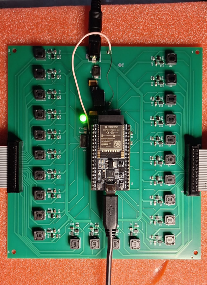
1. 24-LED Control Board
Power and Regulation Module
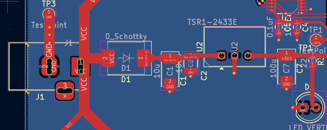
This module converts the main 12V input into a stable 3.3V supply to power the ESP32 microcontroller and the PCA9685 PWM drivers.
- Regulator: It uses a TSR1-2433E buck switching converter for high energy efficiency.
- Protection: A D1 diode protects the circuit against reverse polarity.
- Diagnostics: A green LED (D2) indicates when the system is powered.
Microcontroller (ESP32)
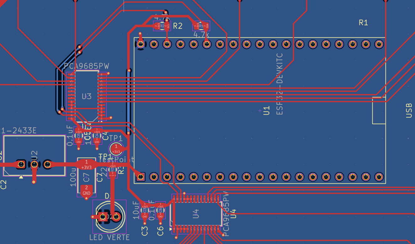
The ESP32 executes the embedded program and transmits brightness instructions via I2C (SDA/SCL). Pull-up resistors (R1, R2) ensure stable data transmission.
PWM Drivers (PCA9685)
Two PCA9685PW chips generate 24 stable PWM signals at 400 Hz.
- Addressing: Driver 1 (U3) is at 0x40; Driver 2 (U4) is at 0x41.
- Stability: Decoupling capacitors (C3-C6) are placed close to the VDD pins.
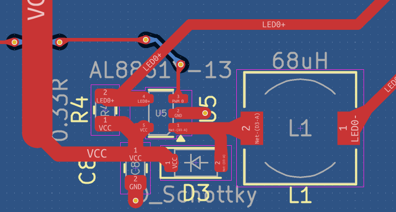
Constant Current LED Drivers (AL8861)
This power stage translates the PWM signals into constant current for the LEDs.
- Efficiency: Uses a Buck switching regulator to minimize heat.
- Current Setting: Nominal current is hardware-defined at 300 mA via a 0.33 Ω resistor (R4).
One of 24
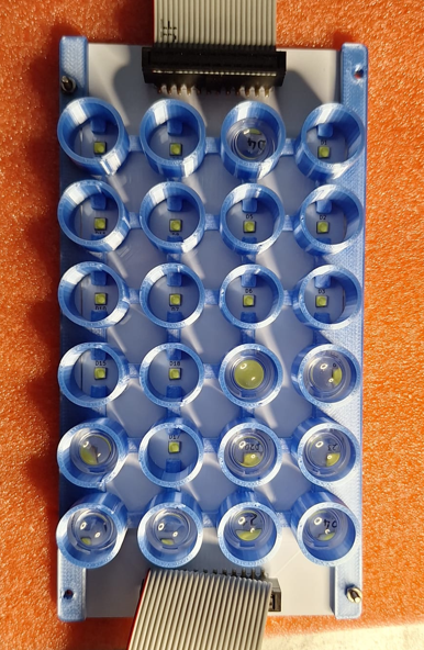
2. LED Plate
This secondary PCB houses the 24 high-power OSLON SSL 80 LEDs
- Thermal Management: Uses an aluminum plate instead of standard FR4 to dissipate intense heat.
- Geometry: LEDs are arranged in a matrix with 19.5 mm spacing to align with the 24-well plate used on the jubilee.
- Optics: Convergent lenses are housed in a custom 3D-printed piece to focus light.
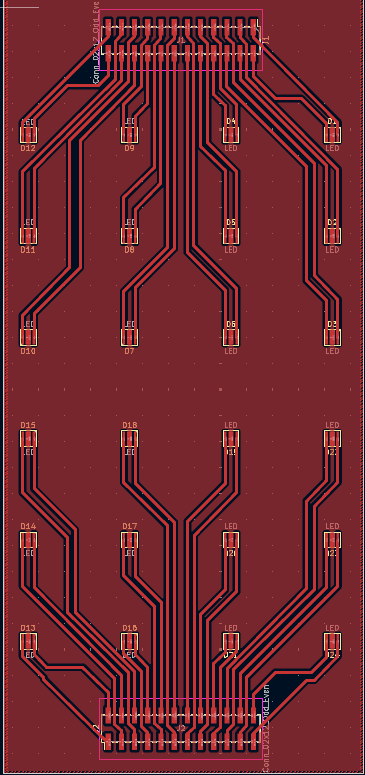
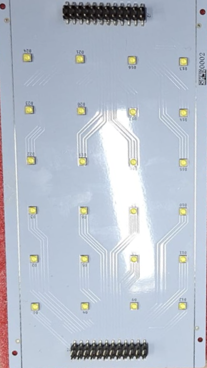
If the LEDs don't light it's probably the orientation of the idc cable try the other way.
(NOTE) Grounding Issue on already printed versions (NOW FIXED ON KICAD)
Issue Description:
The OE pins of the 2 PCA9685 were incorrectly connected via two pull-up resistors ([R28] and [R29]). This configuration causes the PWM signals to not be sent to the AL8861s. The pins actually require a direct connection to Ground (GND) to maintain a stable logic LOW state.
Hardware Rework Instructions:
To apply the fix on existing boards, please follow these steps:
- Remove components: Desolder and completely remove resistors [R28] and [R29].
- Add a jumper wire: Solder a small bodge wire from the OE pin of the two PCA9685 (where the resistors were removed) pad directly to the GND Test Point TP3.
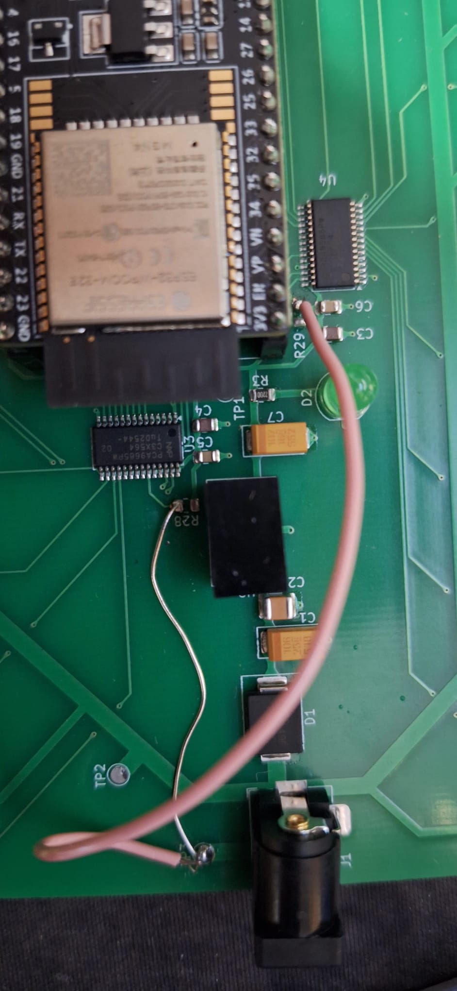
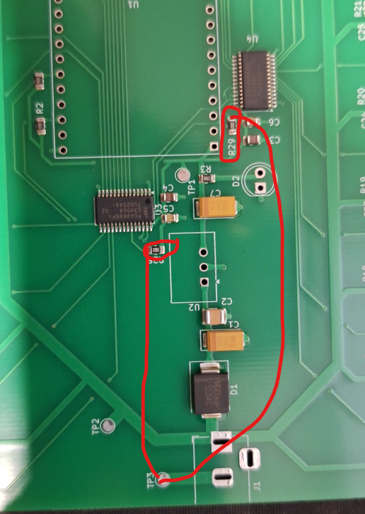
Note: The schematic and PCB layout files have been updated.
3. Soldering
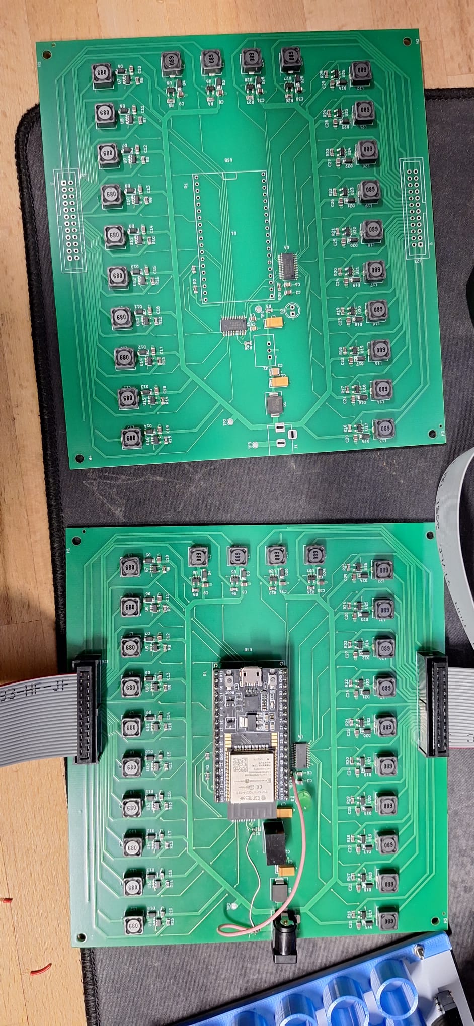
When recieving the printed pcb, THT components will probably not be soldered, you will have to do it yourself.
List of THT components :
- 2 single row 19 female header pins with 2.54 pitch for the ESP32
- The TSR1-2433E
- 2 male IDC headers 12*2 for 24 LEDS (beware of the orientation, special slot towards the outside)
- DC barrel Jack/Connector
- Green LED
4. Ordering (WARNING)
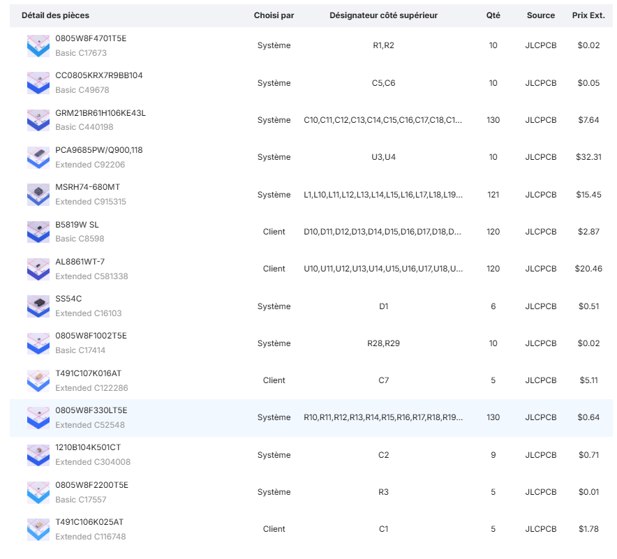
When ordering via JLCPCB for example some SMD components will probably out of stock make sure you use components with similar specs and the right print. For the AL8861, JLCPCB will probably suggest the same component with the wrong print make sure you use the version with the SOT-23-5 package.
The following Bill Of Materials do not contain the THT components and the the IDC cables
(divide quantity by 5 for a single pcb)
Bill of material green pcb
Bill of material white pcb

Ordering with JLCPCB is a lot easier with this kicad plugin
5. SHOWCASE

Documentation & Links


