4 layers53.3 × 68.6 mm
 RaphWeyman/CANPower10
Accessory power controller for BMW CAN bus bikes
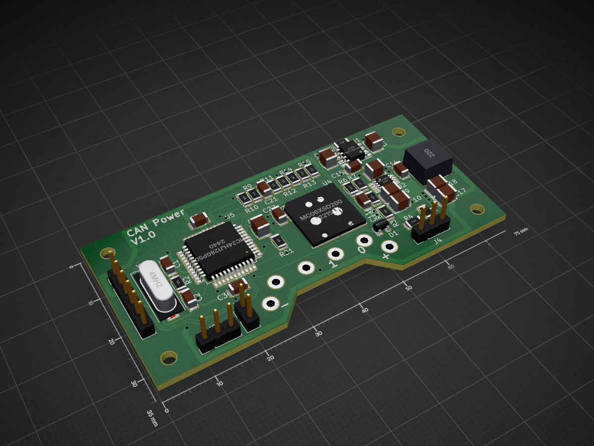
CANPower is an open-source printed circuit board by RaphWeyman, from the RaphWeyman/CANPower repository on GitHub, published under the GPL-2.0 licence. It is a 2-layer board of 75 × 35 mm with 66 parts on 66 nets, routed with 585 tracks and 49 vias.
It is built around the PIC24HJ128GP504-I/ML, MCP2562-E/SN and MCP16311-E/MS, with the MCP1727-3302E/SN and BSS83P among its other parts. Its parts include 23 capacitors, 21 resistors, 7 connectors, 5 ICs and 2 transistors. It belongs with the interfaces and adapters boards and the PIC boards of this library.


Accessory power controller for BMW CAN bus bikes
Two channel power switch using BMW CAN bus messages to control switch output. Microchip PIC24 based.
Hardware is a printed circuit board created and modifiable with KiCAD. If no modifications are required then the gerbers zip file can be used as is to get manufactured. The gerber file names are as required by Elecrow.
The software is packaged as a Microchip PIC IDE project and requires Microchip MPLAB X with the 16 bit PIC compiler installed - all free from the Microchip website.
The 6 way "debug" header on the PCB connects directly to the the Microchip PICKit 3 debugger/programmer. This or some other programmer is required in order to program the software to the Microchip MCU.
Functionality may easily be changed by modifying the application.c file. Here's what the default application does:-
| Qty | Value | Footprint | References |
|---|---|---|---|
| 8 | 100nF | Capacitors_SMD:C_1206 | C3, C5, C14, C15, C19, C20, C22, C29 |
| 6 | 10uF | Capacitors_SMD:C_1210 | C4, C7, C9, C10, C17, C18 |
| 5 | 1M | Resistors_SMD:R_1206 | R2, R3, R19, R20, R21 |
| 4 | Mounting_Holes:MountingHole_2.5mm | , , , | |
| 4 | 100K | Resistors_SMD:R_1206 | R5, R9, R10, R13 |
| 4 | 22nF | Capacitors_SMD:C_1206 | C11, C21, C23, C24 |
| 3 | 2u2 | Capacitors_SMD:C_1210 | C12, C13, C16 |
| 2 | 10K | Resistors_SMD:R_1206 | R1, R7 |
| 2 | 150R | Resistors_SMD:R_1206 | R16, R17 |
| 2 | 20pF | Capacitors_SMD:C_1206 | C1, C2 |
| 2 | 470K | Resistors_SMD:R_1206 | R4, R18 |
| 2 | 8K2 | Resistors_SMD:R_1206 | R12, R14 |
| 2 | BSS83P | TO_SOT_Packages_SMD:SOT-23 | Q1, Q2 |
| 1 | 120R | Resistors_SMD:R_1206 | R8 |
| 1 | 1K | Resistors_SMD:R_1206 | R11 |
| 1 | 22uH | raphfootprints:Coilcraft_MSS7341 | L1 |
| 1 | 2A | Resistors_SMD:R_1206 | F1 |
| 1 | 2K2 | Resistors_SMD:R_1206 | R15 |
| 1 | 4MHz | Crystals:Crystal_SMD_HC49-SD | Y1 |
| 1 | 52K3 | Resistors_SMD:R_1206 | R6 |
| 1 | BATT | Wire_Connections_Bridges:WireConnection_1.50mmDrill | J7 |
| 1 | BAV74LT1G | TO_SOT_Packages_SMD:SOT-23 | D1 |
| 1 | CAN | Pin_Headers:Pin_Header_Straight_1x02_Pitch2.54mm | J1 |
| 1 | Debug | Pin_Headers:Pin_Header_Straight_1x06_Pitch2.54mm | J3 |
| 1 | LED | Pin_Headers:Pin_Header_Straight_1x03_Pitch2.54mm | J8 |
| 1 | MC06XSD200 | raphfootprints:QFN-23_12x12mm_Pitch0.9mm_holes | U4 |
| 1 | MCP16311 | Housings_SSOP:MSOP-8_3x3mm_Pitch0.65mm | U2 |
| 1 | MCP1727-3302 | Housings_SOIC:SOIC-8_3.9x4.9mm_Pitch1.27mm | U1 |
| 1 | MCP2562-E/SN | Housings_SOIC:SOIC-8_3.9x4.9mm_Pitch1.27mm | U3 |
| 1 | Output0 | Wire_Connections_Bridges:WireConnection_1.50mmDrill | J5 |
| 1 | Output1 | Wire_Connections_Bridges:WireConnection_1.50mmDrill | J6 |
| 1 | PIC24HJ128GP504 | Housings_QFP:PQFP-44_10x10mm_Pitch0.8mm | U5 |
| 1 | Power | Pin_Headers:Pin_Header_Straight_1x03_Pitch2.54mm | J4 |
It measures 75 × 35 mm and has 2 copper layers, 1.6 mm thick.
66 parts, built around the PIC24HJ128GP504-I/ML, MCP2562-E/SN, MCP16311-E/MS and MCP1727-3302E/SN. The full list of its parts is on this page, with links to each part's symbol and footprint where PCBKit's library has them.
From the RaphWeyman/CANPower repository on GitHub, at the commit this page was made from: the board is Hardware/KiCAD/CANPower/CANPower.kicad_pcb. PCBKit opens the board in the browser, with nothing to install.
Its repository publishes it under the GPL-2.0 licence: you may reuse it on that licence's terms (keep the author's notice, and for a copyleft licence share your changes alike).

frc971/electrical
This repo contains the electrical files for the 971 FRC team. The files include PCBs and the electrical system diagrams. The PCBs are created using KiCad.


victorstoica114/Invertor_board
This repository contains an ESP-IDF firmware for an ESP32 board that bridges, translates, decodes, and exposes battery/inverter communication over CAN and RS485.

cs-pub-ro/smart-solar-irradiance-sensor
Open-source hardware & software for a smart wireless sensor that measures solar irradiance.


mck1117/wr-rusefi
Georgia Tech Wreck Racing's implementation of a Rusefi compatible ECU