
2 layers99.9 × 85.9 mm
Hexapod
quick-brown-bot/hexapod
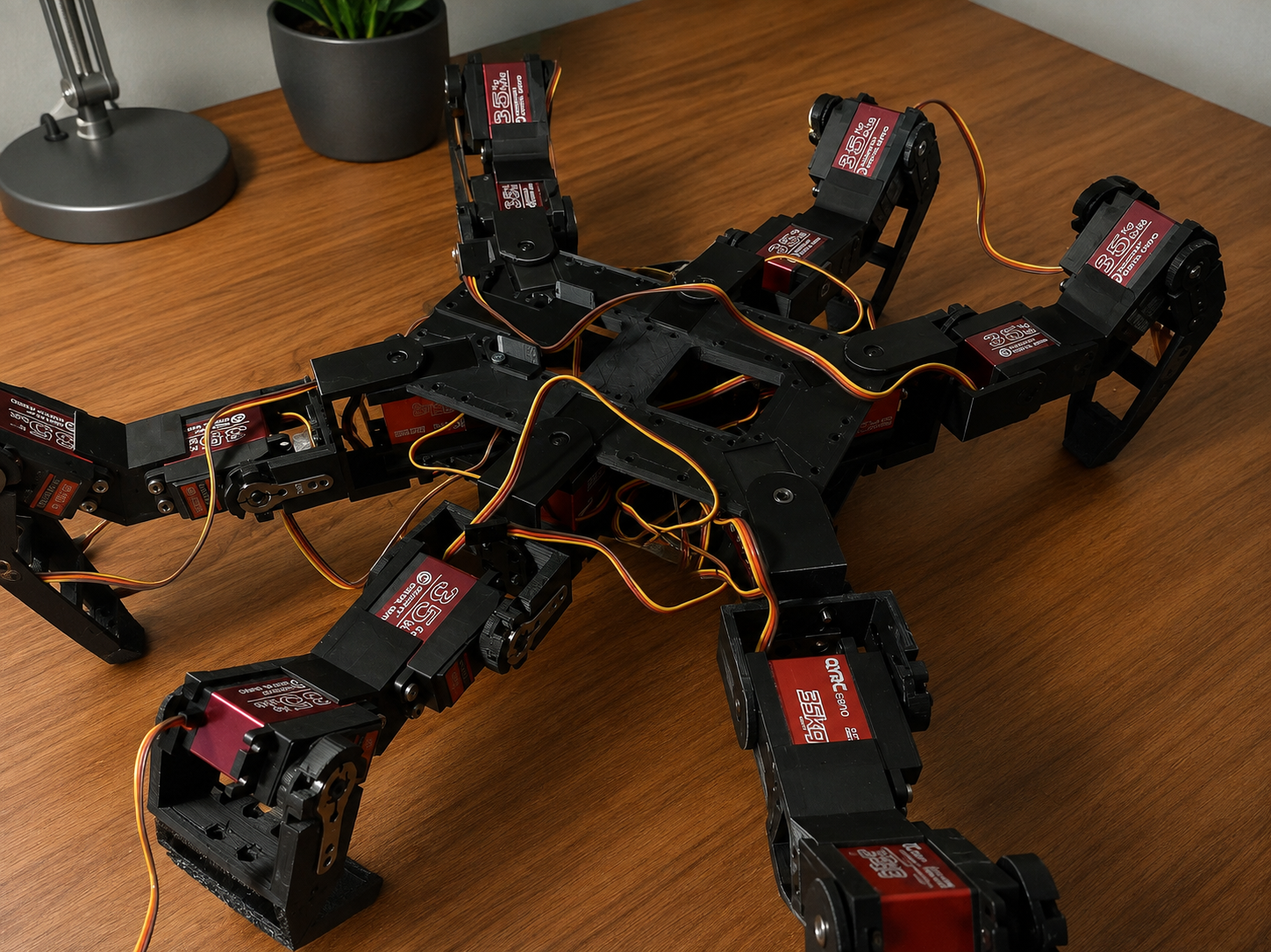
Pawels' hobby - main repository of the code for hexapod. Controller used is ESP32 and the code is based on ESP-IDF framework.
67 parts2

 quick-brown-bot/hexapod2
Pawels' hobby - main repository of the code for hexapod. Controller used is ESP32 and the code is based on ESP-IDF framework.
Esp32 connector is an open-source printed circuit board by quick-brown-bot, from the quick-brown-bot/hexapod repository on GitHub. It is a 2-layer board of 41.7 × 49 mm with 10 parts on 31 nets, routed with 130 tracks and 18 vias.
It is built around the ESP32-WROOM-32D. Its parts include 3 connectors, 2 capacitors, 2 diodes, 1 resistor and 1 IC. It belongs with the ESP32 boards of this library.
This is the old (V1) version of the project. Active development has moved to V2: quick-brown-bot/hexapod_v2. This repo is closed — kept for reference and continued use, not further development.
An ESP32-powered hexapod robot built as a long-term robotics and embedded systems project.
The goal is not just to make a robot walk, but to learn and at the same time build a platform that is easy to experiment with, tune, and extend. Most robot behavior is configurable at runtime, control inputs are transport-independent, and the motion stack is organized into separated components.
The project combines firmware, hardware design, and system documentation in a single repository.
6 legs, 18 servos, ESP32, ESP-IDF, FreeRTOS, direct PWM.
The distributed RS485/RP2040 leg-controller generation of this project has moved to a separate repository: quick-brown-bot/hexapod_v2. This repo covers the original ESP32 direct-PWM robot only. V1 is closed: the hardware and firmware here are done and kept for reference and continued use, not further development.
The repository contains software and hardware assets used to develop and validate the robot.
firmware/
└── mainboard/         Main robot firmware (ESP32, direct PWM)

hardware/
├── servo_mainboard/   Central ESP32 board driving the servos directly
├── leg/               Leg controller board
├── esp32_connector/   ESP32 carrier / breakout
├── symbols/           Symbol libraries
├── footprints/        Footprint libraries
└── models/            Mechanical models

docs/
├── common/            Docs shared across subsystems (RPC, WiFi, config)
├── architecture/       System and hardware architecture docs
├── development/        Development docs
└── plans/             Project-wide backlog and research items
Mainboard firmware overview: firmware/mainboard/README.md
The main firmware is built around a fixed 100 Hz control loop and a modular motion pipeline:
Controller Input
        ↓
Gait Scheduler
        ↓
Foot Trajectory Generation
        ↓
Inverse Kinematics
        ↓
Motion Limiting
        ↓
Servo Outputs| Effort Area | Scope | Current Status | Notes |
|---|---|---|---|
| Locomotion Pipeline | Command mapping, gait scheduler, swing trajectory, whole-body IK | Implemented | Runs in a fixed 100 Hz control loop |
| KPP Motion Limits | Velocity, acceleration, jerk limiting and state estimation | Implemented | Runtime limits are configuration-backed |
| Controller Abstraction | Driver-agnostic core plus transport-specific drivers | Implemented | FlySky iBUS, Wi-Fi TCP, and Bluetooth Classic paths are present |
| RPC System | Queue-based command processing and config control | Implemented | Live inspection and runtime tuning are available |
| Configuration Platform | Namespace defaults, migration, discovery, persistence | Implemented | Core runtime namespaces are already consumed by modules |
| Configurator Tooling | External tuning and visualization UX | Planned | Firmware-side groundwork exists; UI work remains |
flowchart LR
        Control[Controller stack]
        Config[RPC and config]
        App[Application loop]
        Loc[Locomotion]
        Limits[Motion limiting]
        Act[Actuation]
        Robot[Robot hardware]

        Control --> App
        Config --> App
        App --> Loc --> Limits --> Act --> Robot
Config --> ControlConfiguration is treated as a first-class subsystem rather than a collection of compile-time constants.
Parameters are organized into namespaces. Each namespace owns:
The configuration manager provides:
Robot geometry, calibration data, controller settings, motion limits, and other runtime behavior are loaded through this system rather than being hardcoded throughout the codebase.
The locomotion stack converts user commands into joint targets through a sequence of dedicated subsystems:
The motion loop runs at 100 Hz.
Controller transports are separated from locomotion.
Supported ingress paths currently include:
Each transport driver translates incoming data into a normalized controller state consumed by the motion system.
This allows locomotion, gait generation, and motion limiting to remain independent of transport-specific protocols.
The robot uses 18 servos arranged as three joints per leg:
Servo signal generation is implemented on ESP32 using a combination of MCPWM and LEDC peripherals to fit within available hardware resources.
Power for logic and servos is separated to improve stability under heavy load.
This project is primarily a learning and engineering platform.
Current focus areas include:
The repository contains detailed documentation covering implementation details and architecture decisions.
Common:
Full documentation index: docs/README.md
The project is under active development.
Current work focuses on improving locomotion quality, refining control architecture boundaries, and preparing the next generation of leg electronics while keeping the existing robot operational as a test platform.
This repository uses Apache License 2.0 for the mainboard firmware.
License file location: LICENSE
Include the following notice in derivative works:
Copyright 2025 Pawel Grudzien

Licensed under the Apache License, Version 2.0 (the "License");
you may not use this file except in compliance with the License.
You may obtain a copy of the License at

    http://www.apache.org/licenses/LICENSE-2.0

Unless required by applicable law or agreed to in writing, software
distributed under the License is distributed on an "AS IS" BASIS,
WITHOUT WARRANTIES OR CONDITIONS OF ANY KIND, either express or implied.
See the License for the specific language governing permissions and
limitations under the License.| Qty | Value | Footprint | References |
|---|---|---|---|
| 1 | Barrel_Jack | TerminalBlock_Phoenix:TerminalBlock_Phoenix_MKDS-1,5-2_1x02_P5.00mm_Horizontal | J2 |
| 1 | C_100_nF | Capacitor_SMD:C_0805_2012Metric | C2 |
| 1 | C_10_µF | Capacitor_SMD:C_1206_3216Metric | C1 |
| 1 | Conn_01x18 | Connector_FFC-FPC:TE_1-84952-8_1x18-1MP_P1.0mm_Horizontal | J1 |
| 1 | D_Schottky | Diode_SMD:D_SOD-123 | D2 |
| 1 | ESP32-WROOM-32D | Library:ESP32_Dev_Board | U1 |
| 1 | LED_Small | LED_SMD:LED_0805_2012Metric | D1 |
| 1 | R_Small | Resistor_SMD:R_0805_2012Metric | R1 |
| 1 | Reveiver | Connector_PinHeader_2.54mm:PinHeader_1x03_P2.54mm_Vertical | J23 |
The 9 most common of 10 parts.
quick-brown-bot/hexapod
Pawels' hobby - main repository of the code for hexapod. Controller used is ESP32 and the code is based on ESP-IDF framework.

W0rthlessS0ul/nRF24_jammer
The nRF24 jammer is a powerful tool that requires an ESP32 and configurable numbers of NRF24 modules to assemble.


doudar/SmartSpin2k
Transform your spin bike into a Smart Trainer!


voltlog/Valve-Actuator
If you are looking for sources of previous revisions (revA, revB, revC) checkout the different branches of this repo.

Jutta-Proto/protocol-cpp
C++ JURA protocol implementation for controlling a Jura coffee maker over a serial (UART) connection.


It measures 41.7 × 49 mm and has 2 copper layers, 1.6 mm thick.
10 parts, built around the ESP32-WROOM-32D. The full list of its parts is on this page, with links to each part's symbol and footprint where PCBKit's library has them.
From the quick-brown-bot/hexapod repository on GitHub, at the commit this page was made from: the board is hardware/esp32_connector/esp32_connector.kicad_pcb and its schematic hardware/esp32_connector/esp32_connector.kicad_sch. PCBKit opens the board in the browser, with nothing to install.
Its repository states no licence, so its author keeps all rights: ask quick-brown-bot before reusing the design.