4 layers49.3 × 45.4 mm

 kbx81/kbxIRBlaster58
ESP32-based IR MegaBlaster!
KbxIrBlaster is an open-source printed circuit board by kbx81, from the kbx81/kbxIRBlaster repository on GitHub, published under the CC-BY-SA-4.0 licence. It is a 2-layer board of 22 × 66.5 mm with 106 parts on 84 nets, routed with 723 tracks and 33 vias.
It is built around the ESP32-WROOM-32D, FT232RL and AP2112K-3.3, with the MBR120 and MMSS8050-H among its other parts. Its parts include 30 diodes, 25 resistors, 9 capacitors, 8 connectors and 7 transistors. It belongs with the ESP32 boards of this library.


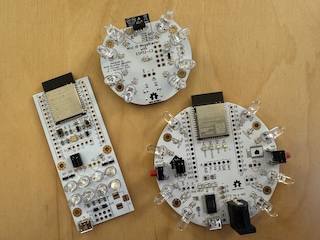
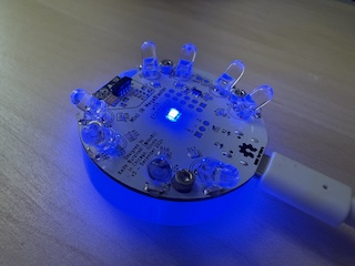
Just another ESP32-based IR Blaster. It was designed with ESPHome in mind but should work fine with Tasmota or any other app, really.
I've created four versions:
See the gallery for more images.
After trying this on a perfboard with parts I had laying around, I wanted something more polished and more powerful. I found Sparkfun's IR Blaster which is quite nice, tiny and clean but I quickly realized that its IR output is somewhat weak and would only work if pointed directly at the device it was intended to control. Rather than hack it up, I chose to draw up my own versions of such a thing. My goal was to make them substantially more powerful in an effort to "light up a room" with infrared light; that is, you'll probably find that they work well even when not specifically directed at (if even near) devices you wish to control. I've used an ESP32 module instead of an ESP8266, as the ESP32 (and its variants) has dedicated hardware for IR data transmission (the RMT) which makes it more suitable for this purpose, despite that it's otherwise quite overkill.
Please see the bill of materials (BoM) for the version of interest:
I had the PCBs fabricated by Elecrow but nearly any PCB fabricator should be able to manufacture these without any issues. I do recommend white soldermask as it will reflect IR best.
The schematic and PCB were drawn in KiCad.
The v1 and v2 PCBs have a number of solder jumpers on the bottom side that enable each of the FET drivers to be connected to one of two possible GPIO pins. This allows a single GPIO pin to control all LEDs simultaneously or they can be broken apart onto separate GPIO pins. Labels on the underside of the PCBs indicate what jumpers are connected to what LEDs.
Note that the solder jumpers must be bridged one way or the other; if this is not done, the FETs (and consequently the LEDs they drive) will not activate! When you build one, be sure to complete this step or you'll be left in the dark. (Punny, I know.)
An FS1000A (such as this one) or similar 433 MHz transmitter module may be connected as indicated on the PCB allowing the device to double as an RF remote controller. On the v1 PCB, bridge JP6 to enable this and then connect the module to pins 4, 5, and 6 on J2. On the v2 PCB, simply connect the transmitter to J8. When doing so, be sure to orient the module correctly or tragedy may result.
See my ESPHome-configs repository for example ESPHome configuration you may use with your IR blaster. Enjoy!
The circuit schematics and PCB found here are licensed under the Creative Commons Attribution-ShareAlike 4.0 International License.

Happy building!
| Qty | Value | Footprint | References |
|---|---|---|---|
| 8 | 100 | Resistor_SMD:R_0805_2012Metric | R9, R10, R11, R12, R13, R14, R15, R16 |
| 6 | 10K | Resistor_SMD:R_0805_2012Metric | R17, R18, R21, R23, R24, R25 |
| 5 | 2K7 | Resistor_SMD:R_0805_2012Metric | R5, R6, R7, R8, R22 |
| 5 | 2N7002 | Package_TO_SOT_SMD:SOT-23 | Q1, Q2, Q3, Q4, Q7 |
| 4 | - | MountingHole:MountingHole_2.5mm_Pad_Via | H1, H2, H3, H4 |
| 4 | 10 uF | Capacitor_SMD:C_0805_2012Metric | C2, C3, C4, C9 |
| 3 | 100 nF | Capacitor_SMD:C_0805_2012Metric | C6, C7, C8 |
| 3 | CH1 | LED_SMD:LED_0805_2012Metric | D5, D9, D17 |
| 3 | CH2 | LED_SMD:LED_0805_2012Metric | D6, D11, D19 |
| 3 | CH3 | LED_SMD:LED_0805_2012Metric | D7, D13, D21 |
| 3 | CH4 | LED_SMD:LED_0805_2012Metric | D8, D15, D23 |
| 3 | MBR120 | Diode_SMD:D_SOD-123F | D25, D26, D28 |
| 2 | 1K2 | Resistor_SMD:R_0805_2012Metric | R4, R20 |
| 2 | CH1 | LED_THT:LED_D5.0mm | D10, D18 |
| 2 | CH2 | LED_THT:LED_D5.0mm | D12, D20 |
| 2 | CH3 | LED_THT:LED_D5.0mm | D14, D22 |
| 2 | CH4 | LED_THT:LED_D5.0mm | D16, D24 |
| 2 | IO | Connector_PinHeader_2.54mm:PinHeader_1x15_P2.54mm_Vertical | J6, J7 |
| 2 | LOGO | project_footprints:ESPHome_slik_logo | G***, G*** |
| 2 | LOGO | project_footprints:HomeAssistant_slik_logo | G***, G*** |
| 2 | MMSS8050 | Package_TO_SOT_SMD:SOT-23 | Q5, Q6 |
| 2 | TSOP382xx | OptoDevice:Vishay_MINICAST-3Pin | U4, U5 |
| 1 | 1 uF | Capacitor_SMD:C_0805_2012Metric | C1 |
| 1 | 120 | Resistor_SMD:R_0805_2012Metric | R3 |
| 1 | 1K6 | Resistor_SMD:R_0805_2012Metric | R2 |
| 1 | 3V3 | LED_SMD:LED_0805_2012Metric | D2 |
| 1 | 4.7 uF | Capacitor_SMD:C_0805_2012Metric | C5 |
| 1 | 4K7 | Resistor_SMD:R_0805_2012Metric | R19 |
| 1 | 5 TO 6 VDC | Connector_BarrelJack:BarrelJack_Horizontal | J3 |
| 1 | 5V | LED_SMD:LED_0805_2012Metric | D1 |
| 1 | 5V/3V3 | Jumper:SolderJumper-3_P1.3mm_Open_RoundedPad1.0x1.5mm | JP6 |
| 1 | 8K2 | Resistor_SMD:R_0805_2012Metric | R1 |
| 1 | AP2112K-3.3 | Package_TO_SOT_SMD:SOT-23-5 | U2 |
| 1 | ESP32-WROOM-32D | RF_Module:ESP32-WROOM-32 | U1 |
| 1 | EXT_IR | Connector_PinHeader_2.54mm:PinHeader_1x02_P2.54mm_Vertical | J5 |
| 1 | FT232RL | Package_SO:SSOP-28_5.3x10.2mm_P0.65mm | U3 |
| 1 | I34/U4 | Jumper:SolderJumper-2_P1.3mm_Open_RoundedPad1.0x1.5mm | JP7 |
| 1 | I35/U5 | Jumper:SolderJumper-2_P1.3mm_Open_RoundedPad1.0x1.5mm | JP8 |
| 1 | IO0 | Button_Switch_THT:SW_Tactile_SPST_Angled_PTS645Vx58-2LFS | SW2 |
| 1 | IO12/IO14 | Jumper:SolderJumper-3_P1.3mm_Open_RoundedPad1.0x1.5mm | JP2 |
| 1 | IO12/IO16 | Jumper:SolderJumper-3_P1.3mm_Open_RoundedPad1.0x1.5mm | JP3 |
| 1 | IO12/IO17 | Jumper:SolderJumper-3_P1.3mm_Open_RoundedPad1.0x1.5mm | JP4 |
| 1 | IO12/IO2 | Jumper:SolderJumper-3_P1.3mm_Open_RoundedPad1.0x1.5mm | JP5 |
| 1 | IO12/IO27 | Jumper:SolderJumper-3_P1.3mm_Open_RoundedPad1.0x1.5mm | JP1 |
| 1 | N/A | Connector_USB:USB_Micro-B_Molex-105017-0001 | J2 |
| 1 | POWER | Connector_PinHeader_2.54mm:PinHeader_1x02_P2.54mm_Vertical | J1 |
| 1 | RESET | Button_Switch_THT:SW_Tactile_SPST_Angled_PTS645Vx58-2LFS | SW1 |
| 1 | RF/PIR | Connector_PinHeader_2.54mm:PinHeader_1x03_P2.54mm_Vertical | J8 |
| 1 | RX | LED_SMD:LED_0805_2012Metric | D29 |
| 1 | SERIAL | Connector_PinHeader_2.54mm:PinHeader_1x06_P2.54mm_Vertical | J4 |
| 1 | STATUS | LED_SMD:LED_0805_2012Metric | D3 |
| 1 | TX | LED_SMD:LED_0805_2012Metric | D27 |
| 1 | USER | LED_SMD:LED_0805_2012Metric | D4 |
| 1 | VBUS | LED_SMD:LED_0805_2012Metric | D30 |
The 102 most common of 106 parts.


kbx81/ClimateSprinklerController
ESP32-based climate and sprinkler controller for use with ESPHome

oomlout/oomlout_oomp_project_bot_v_2

adilet2109/current-sensor
Bare-metal code base for current sensor board


MUBARIS-KT/DC-DC_CONVERTER
This project provides the complete design and code for a DC to DC converter that steps up 12V DC to 300V DC. The project is a comprehensive solution in power electronics, including PCB design, STM32 code for PWM…

vul-os/sirboard
Open hardware: 107 KiCad PCB designs — SMD-to-THT breakout adapters, ATTiny/ATMega/ESP development boards, and a 39-part sensor line on a common JST-SH connector.


jpconstantineau/NRF52-Board
This Repository is a collection of NRF5x boards.
It measures 22 × 66.5 mm and has 2 copper layers, 1.6 mm thick.
106 parts, built around the ESP32-WROOM-32D, FT232RL, AP2112K-3.3 and MBR120. The full list of its parts is on this page, with links to each part's symbol and footprint where PCBKit's library has them.
From the kbx81/kbxIRBlaster repository on GitHub, at the commit this page was made from: the board is v2/kbxIrBlaster.kicad_pcb and its schematic v3/kbxIrBlaster.kicad_sch. PCBKit opens the board in the browser, with nothing to install.
Its repository publishes it under the CC-BY-SA-4.0 licence: you may reuse it on that licence's terms (keep the author's notice, and for a copyleft licence share your changes alike).