2 layers99.5 × 90.5 mm

 maplerainresearch/MRR_ESPA59
A basic 3D printer control board based on ESP32
MRR ESPA is an open-source printed circuit board by maplerainresearch, from the maplerainresearch/MRR_ESPA repository on GitHub. It is a 2-layer board of 99.5 × 90.5 mm with 130 parts on 112 nets, routed with 1,494 tracks and 437 vias.
It is built around the 74LVC1G125, CH340C and ESP32-WROOM-32D, with the TPS54340DDA, AMS1117-3.3 and TLP182(E among its other parts. Its parts include 32 resistors, 20 capacitors, 16 connectors, 15 diodes and 11 ICs. It belongs with the radio and wireless and robots and motor control boards and the ESP32 boards of this library.


This is a bare-minimum 3D printer control board based on the ESP32 microcontroller, which comes with built-in WiFi and BlueTooth.
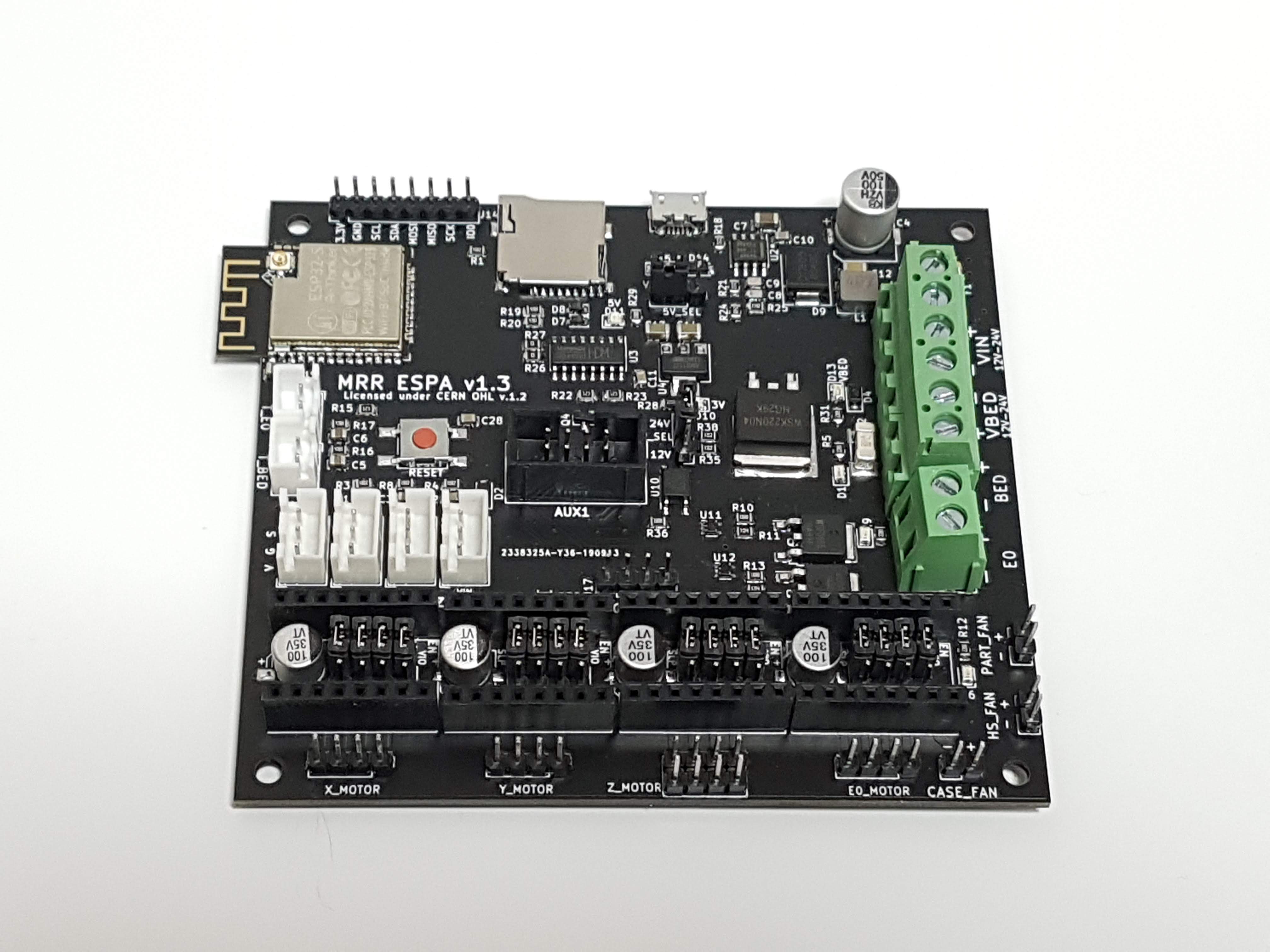 Current version: v1.3
Get a pre-launch version at our store.
Facebook page
Facebook group (for discussions, etc.)
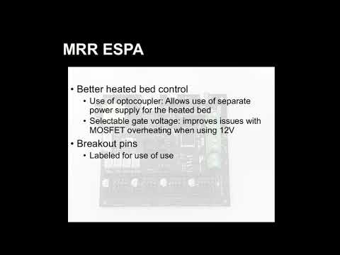
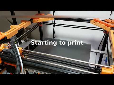
Check out the Kickstarter page.
Marlin 2.0 has added support for ESP32. This board was based on the initial pins definition used.
In addition, Luc has been working on a Marlin fork which incorporates part of his ESP3D webUI into Marlin itself.
See separate PIN_DEF.txt file.
Released under CERN Open Hardware Licence v1.2. See LICENSE.txt for details.
This product is provided as-is. While care has been taken to design a safe product, it is the user's responsibility to make sure precautions are taken to prevent damage or injury when using this product. This includes adhering to all warnings provided. By using this product, the user accepts responsibility to bear all liabilities from any damage or injury arising from the use of this product.
| Qty | Value | Footprint | References |
|---|---|---|---|
| 5 | 10K | Resistor_SMD:R_0805_2012Metric | R1, R3, R4, R8, R32 |
| 5 | 2.2K | Resistor_SMD:R_0805_2012Metric | R5, R9, R12, R30, R31 |
| 4 | 100nF25V | Capacitor_SMD:C_0805_2012Metric | C1, C2, C3, C28 |
| 4 | 100uF35V | Capacitor_SMD:CP_Elec_6.3x7.7 | C15, C16, C17, C18 |
| 4 | 4.7K | Resistor_SMD:R_0805_2012Metric | R16, R17, R19, R20 |
| 4 | MountingHole | MountingHole:MountingHole_3.2mm_M3_DIN965 | H1, H2, H3, H4 |
| 4 | Pololu_board | Module:Pololu_Breakout-16_15.2x20.3mm | U5, U6, U8, U9 |
| 3 | 12K | Resistor_SMD:R_0805_2012Metric | R15, R22, R23 |
| 2 | 0R | Resistor_SMD:R_0805_2012Metric | R26, R27 |
| 2 | 100K | Resistor_SMD:R_0805_2012Metric | R11, R14 |
| 2 | 10R | Resistor_SMD:R_0805_2012Metric | R10, R13 |
| 2 | 1K | Resistor_SMD:R_0805_2012Metric | R35, R38 |
| 2 | 1N4007W | projfp:D_SOD-123F | D4, D5 |
| 2 | 1N5819W | Diode_SMD:D_SOD-123 | D14, D15 |
| 2 | 22uF6.3V | Capacitor_SMD:C_0805_2012Metric | C5, C6 |
| 2 | 330R | Resistor_SMD:R_0805_2012Metric | R29, R36 |
| 2 | 47uF6.3V | Capacitor_SMD:C_0805_2012Metric | C13, C14 |
| 2 | 74LVC1G125 | Package_TO_SOT_SMD:SOT-353_SC-70-5 | U11, U12 |
| 2 | PESD5V0S1BA | projfp:D_SOD-323 | D7, D8 |
| 2 | S9014 | Package_TO_SOT_SMD:SOT-23 | Q4, Q5 |
| 1 | 100nF50V | Capacitor_SMD:C_0805_2012Metric | C10 |
| 1 | 100uF50V | Capacitor_SMD:CP_Elec_8x10 | C4 |
| 1 | 100uF6.3V | Capacitor_SMD:C_1206_3216Metric | C19 |
| 1 | 10nF50V | Capacitor_SMD:C_0805_2012Metric | C11 |
| 1 | 11.5K | Resistor_SMD:R_0805_2012Metric | R25 |
| 1 | 15A 2410 | projfp:Littelfuse_0451 | F1 |
| 1 | 1N4148W | projfp:D_SOD-123 | D2 |
| 1 | 220R | Resistor_SMD:R_0805_2012Metric | R28 |
| 1 | 23.7K | Resistor_SMD:R_0805_2012Metric | R21 |
| 1 | 30A 3912 | projfp:Littelfuse_456 | F2 |
| 1 | 4.7uF50V | Capacitor_SMD:C_1206_3216Metric | C7 |
| 1 | 4.7uH4.5A | projfp:SMMS0530 | L1 |
| 1 | 47uF16V | Capacitor_SMD:C_1206_3216Metric | C12 |
| 1 | 56pF50V | Capacitor_SMD:C_0805_2012Metric | C9 |
| 1 | 5V_SEL | Connector_PinHeader_2.54mm:PinHeader_1x03_P2.54mm_Vertical | JP17 |
| 1 | 60.4K | Resistor_SMD:R_0805_2012Metric | R24 |
| 1 | 73.2K | Resistor_SMD:R_0805_2012Metric | R18 |
| 1 | 820pF50V | Capacitor_SMD:C_0805_2012Metric | C8 |
| 1 | AMS1117-3.3 | Package_TO_SOT_SMD:SOT-223-3_TabPin2 | U4 |
| 1 | AUX1 | Connector_IDC:IDC-Header_2x04_P2.54mm_Vertical | J15 |
| 1 | B540C-13-F | projfp:D_SMC | D9 |
| 1 | BED | TerminalBlock_Phoenix:TerminalBlock_Phoenix_MKDS-3-2-5.08_1x02_P5.08mm_Horizontal | J3 |
| 1 | CH340C | Package_SO:SOIC-16_3.9x9.9mm_P1.27mm | U3 |
| 1 | CS_PINS | Connector_PinHeader_2.54mm:PinHeader_1x04_P2.54mm_Vertical | J17 |
| 1 | E0 | TerminalBlock_Phoenix:TerminalBlock_Phoenix_MKDS-1,5-2-5.08_1x02_P5.08mm_Horizontal | J7 |
| 1 | E0_MOTOR | Connector_PinHeader_2.54mm:PinHeader_1x04_P2.54mm_Vertical | J24 |
| 1 | E0_MS1 | Connector_PinHeader_2.54mm:PinHeader_1x03_P2.54mm_Vertical | JP4 |
| 1 | E0_MS2 | Connector_PinHeader_2.54mm:PinHeader_1x03_P2.54mm_Vertical | JP8 |
| 1 | E0_MS3 | Connector_PinHeader_2.54mm:PinHeader_1x03_P2.54mm_Vertical | JP12 |
| 1 | E0_RST | Connector_PinHeader_2.54mm:PinHeader_1x03_P2.54mm_Vertical | JP16 |
| 1 | ESP32-WROOM-32D | RF_Module:ESP32-WROOM-32 | U1 |
| 1 | FAN_CASE | Connector_PinHeader_2.54mm:PinHeader_1x02_P2.54mm_Vertical | J8 |
| 1 | FAN_HEATSINK | Connector_PinHeader_2.54mm:PinHeader_1x02_P2.54mm_Vertical | J11 |
| 1 | I2C/SPI | Connector_PinHeader_2.54mm:PinHeader_1x08_P2.54mm_Vertical | J14 |
| 1 | LED_3V | projfp:LED_0805 | D10 |
| 1 | LED_5V | projfp:LED_0805 | D11 |
| 1 | LED_BED | projfp:LED_0805 | D1 |
| 1 | LED_E0 | projfp:LED_0805 | D3 |
| 1 | LED_FAN | projfp:LED_0805 | D6 |
| 1 | LED_VBED | projfp:LED_0805 | D13 |
| 1 | LED_VIN | projfp:LED_0805 | D12 |
| 1 | Micro_SD_Card_China | projfp:Conn_uSDcard | J4 |
| 1 | PART_FAN | Connector_PinHeader_2.54mm:PinHeader_1x02_P2.54mm_Vertical | J10 |
| 1 | PWR_IN | TerminalBlock_Phoenix:TerminalBlock_Phoenix_MKDS-3-4-5.08_1x04_P5.08mm_Horizontal | J9 |
| 1 | PWR_SEL | Connector_PinHeader_2.54mm:PinHeader_1x03_P2.54mm_Vertical | JP18 |
| 1 | RESET | projfp:6x6mmTactileSwitch | SW1 |
| 1 | TLP182 | Package_SO:MFSOP6-4_4.4x3.6mm_P1.27mm | U10 |
| 1 | TPS54340DDA | Package_SO:TI_SO-PowerPAD-8_ThermalVias | U2 |
| 1 | T_BED | Connector_JST:JST_XH_B02B-XH-A_1x02_P2.50mm_Vertical | J12 |
| 1 | T_E0 | Connector_JST:JST_XH_B02B-XH-A_1x02_P2.50mm_Vertical | J13 |
| 1 | USB_B_Micro | Connector_USB:USB_Micro-B_Molex-105017-0001 | J16 |
| 1 | WSF3038 | Package_TO_SOT_SMD:TO-252-2 | Q3 |
| 1 | WSF3085 | Package_TO_SOT_SMD:TO-252-2 | Q2 |
| 1 | WSK220N04 | Package_TO_SOT_SMD:TO-263-2 | Q1 |
| 1 | X_MIN | Connector_JST:JST_XH_B03B-XH-A_1x03_P2.50mm_Vertical | J1 |
| 1 | X_MOTOR | Connector_PinHeader_2.54mm:PinHeader_1x04_P2.54mm_Vertical | J21 |
| 1 | X_MS1 | Connector_PinHeader_2.54mm:PinHeader_1x03_P2.54mm_Vertical | JP1 |
| 1 | X_MS2 | Connector_PinHeader_2.54mm:PinHeader_1x03_P2.54mm_Vertical | JP5 |
| 1 | X_MS3 | Connector_PinHeader_2.54mm:PinHeader_1x03_P2.54mm_Vertical | JP9 |
| 1 | X_RST | Connector_PinHeader_2.54mm:PinHeader_1x03_P2.54mm_Vertical | JP13 |
The 117 most common of 130 parts.


rusefi/rusefi
rusefi - GPL internal combustion engine control unit
It measures 99.5 × 90.5 mm and has 2 copper layers, 1.6 mm thick.
130 parts, built around the 74LVC1G125, CH340C, ESP32-WROOM-32D and TPS54340DDA. The full list of its parts is on this page, with links to each part's symbol and footprint where PCBKit's library has them.
From the maplerainresearch/MRR_ESPA repository on GitHub, at the commit this page was made from: the board is current/MRR_ESPA.kicad_pcb. PCBKit opens the board in the browser, with nothing to install.
Its repository states no licence, so its author keeps all rights: ask maplerainresearch before reusing the design.