
2 layers23.7 × 45.2 mm

FFC mod for SnakeOilXY 3-D printer
Mcu2 is an open-source printed circuit board by sadaoikebe, from the sadaoikebe/SnakeOilXY-FFC repository on GitHub, published under the GPL-3.0 licence. It is a 2-layer board of 96.8 × 57.7 mm with 36 parts on 65 nets, routed with 485 tracks and 156 vias.
It is built around the 1N5819WS, KF128-5.0-8P and SMAJ28A, with the WSF3085 among its other parts. Its parts include 10 resistors, 7 diodes, 4 ICs, 3 transistors and 3 connectors. It belongs with the RP2040 boards of this library.


This is a toolhead PCB suite for SnakeOil-XY 3-D printer.

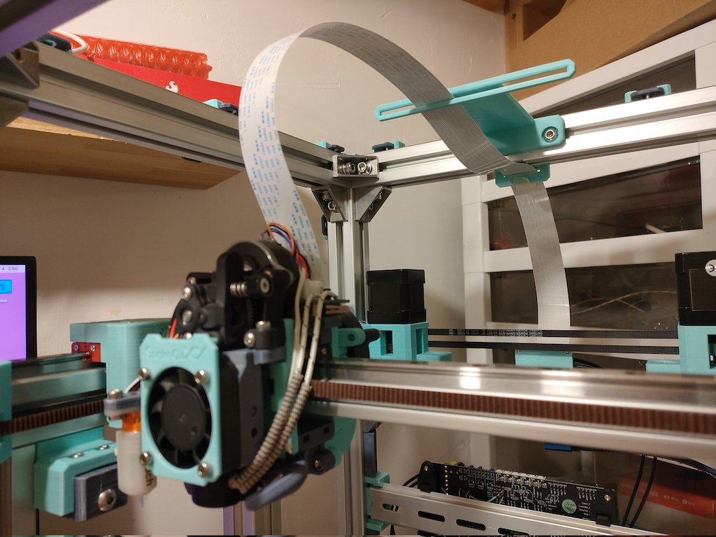
This toolhead PCB can be attached onto adxl_mount to replace the ADXL345 PCB.
It's a toolhead PCB with an ADXL345 accelerometer on-board, and it has an X endstop which fits SnakeOil-XY toolhead dimension.
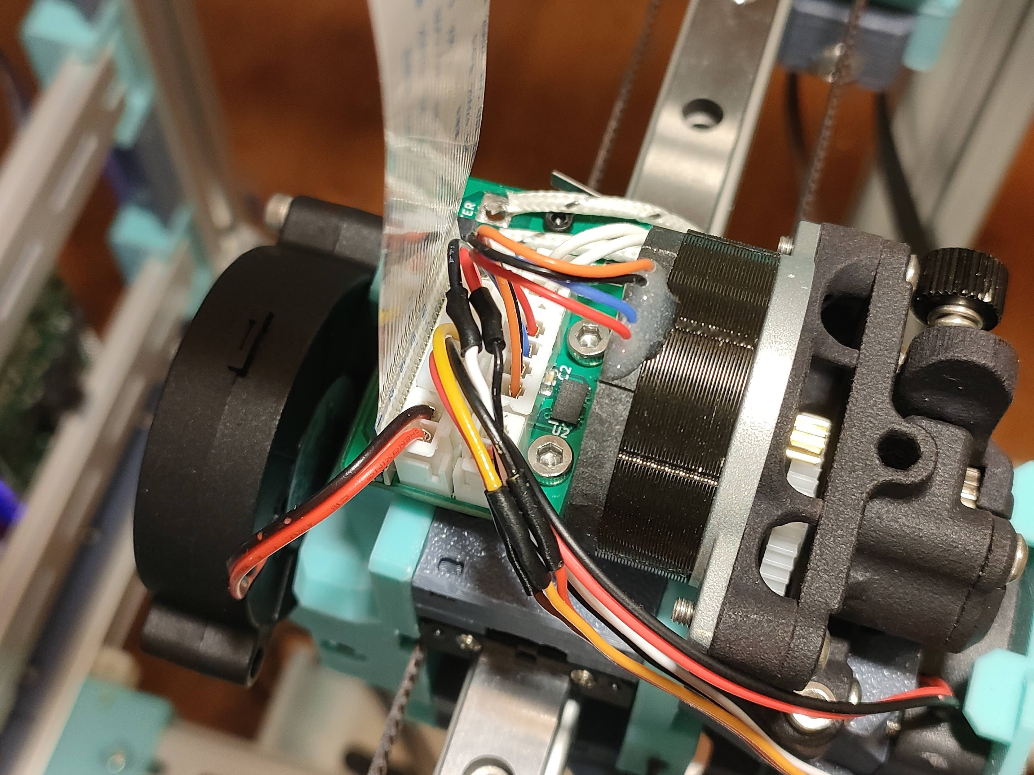
Tricky steps are:


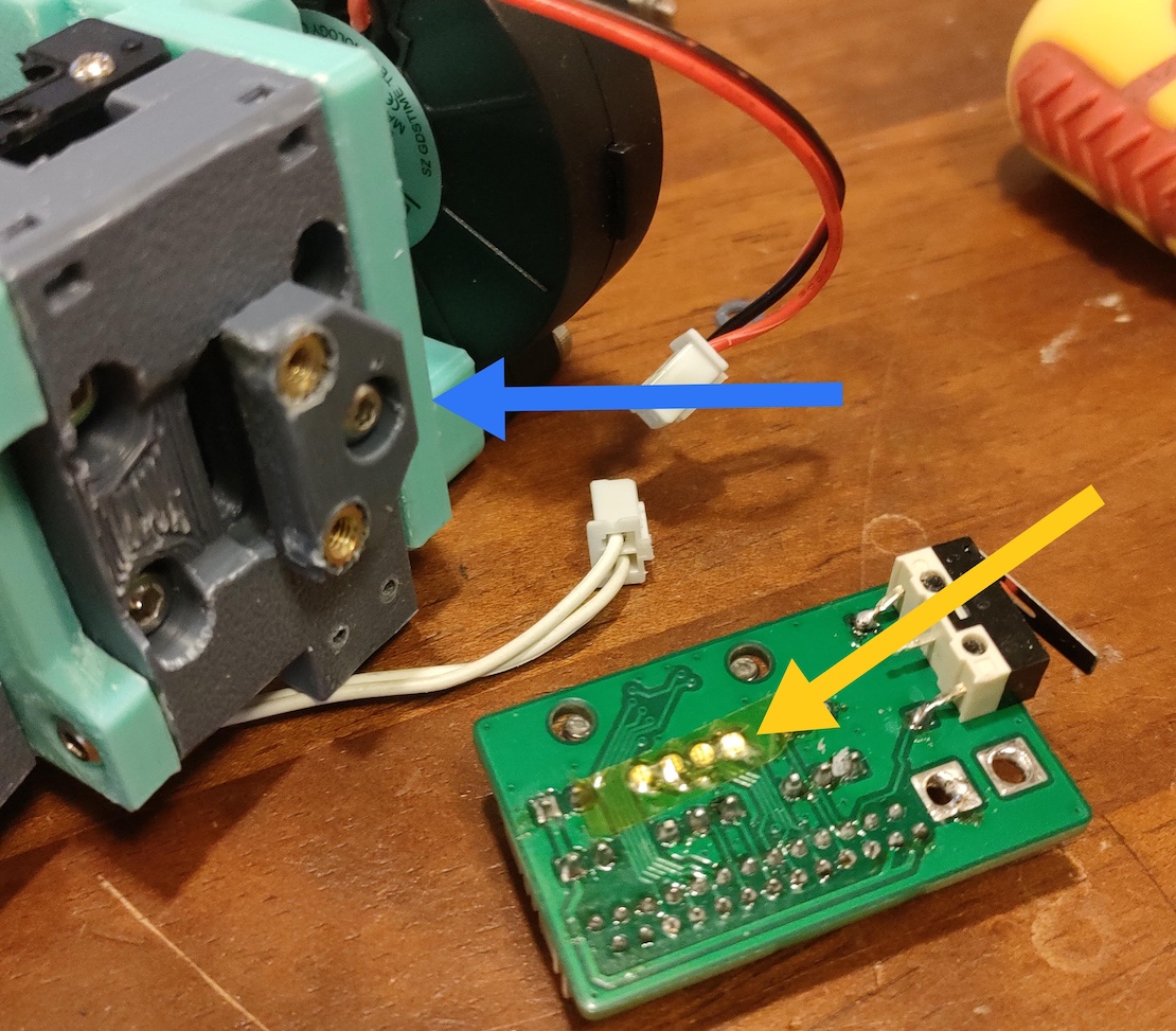
It's designed to mount onto adxl_mount, however the X endstop switch is a bit thicker than the adxl_mount. Print and use spacer in the toolhead folder.
The back side of the stepper connector may touch the M3 bolt underneath the toolhead board. In order to avoid the unwanted contact, I recommend to cut the excess wire on the bottom and apply some capton tape to have better insulation.
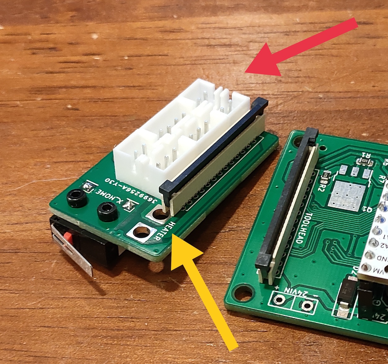
For ease of connection, this board is dedicated to this FFC configuration. The MCU board just needs to be connected to the Raspberry Pi via USB and supplied with 24V power. A 1.0mm pitch 26-pin 20624 FFC cable is used.
It only supports UART-connected smart drivers (like TMC2209) for stepper motor driver. SPI or direct connections are not supported.
FFC connector can be soldered to either the front or back side of the board. Considering cooling and wiring, it's better to place it on the back side.
This board has schottky diode on it, so 24V probe can be connected to Zmin pin without frying the MCU.
Power => Blue LED
Heater and Fan MOSFETs => Yellow LED
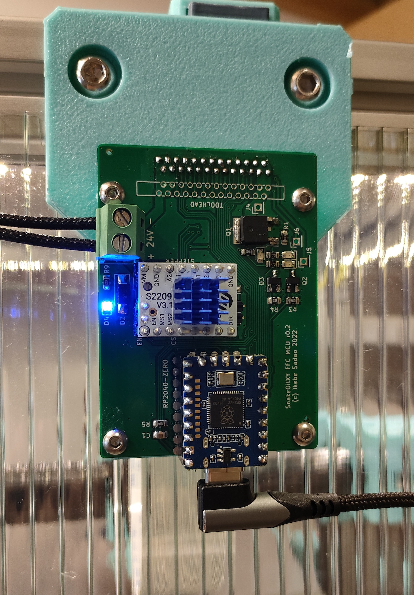
On the rev2 MCU board, the capacitance of C1 is 10uF, which does not stabilize the hotend temperature sensor reading enough. It would be better to add a larger capacitor in parallel or add a smooth_time setting in the [extruder] section.
It assumes multi-mcu functionality of klipper firmware.
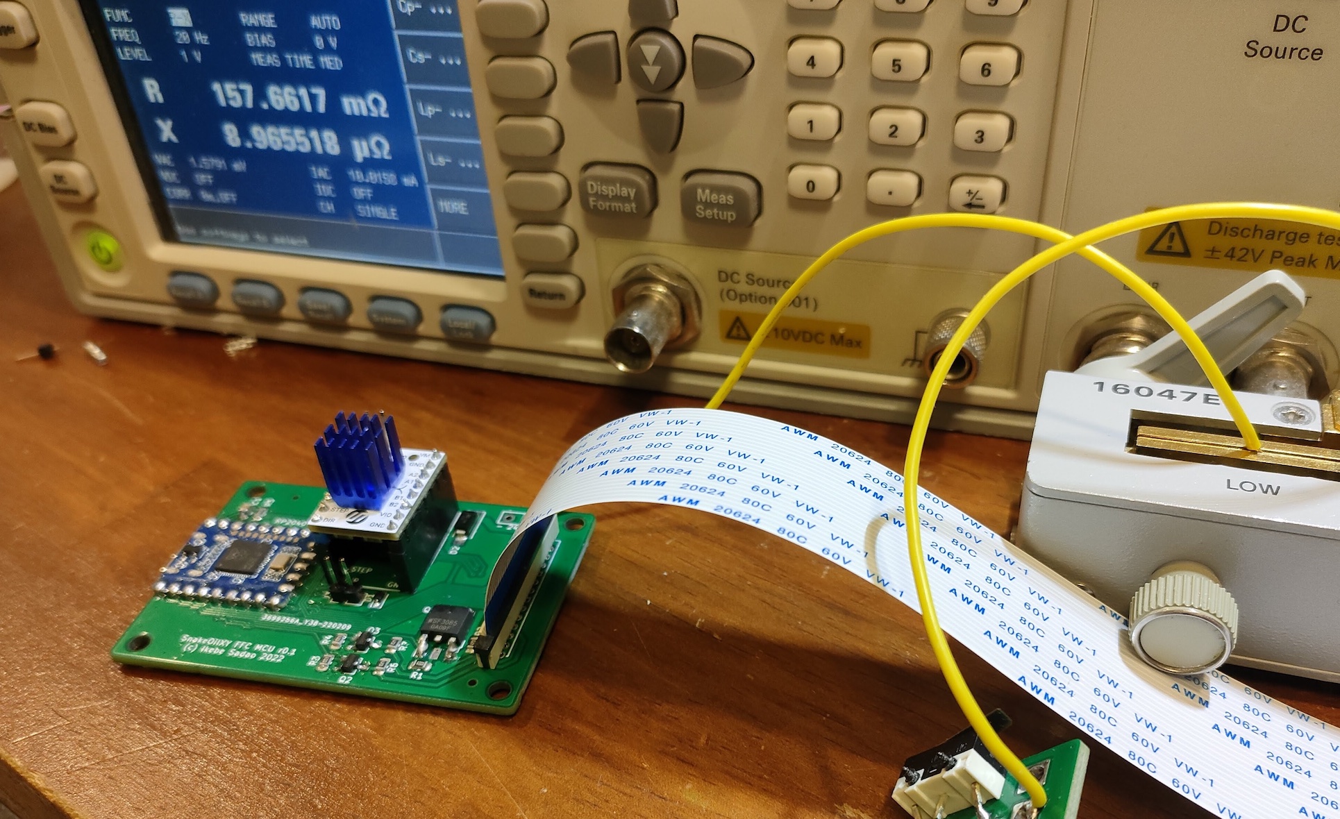
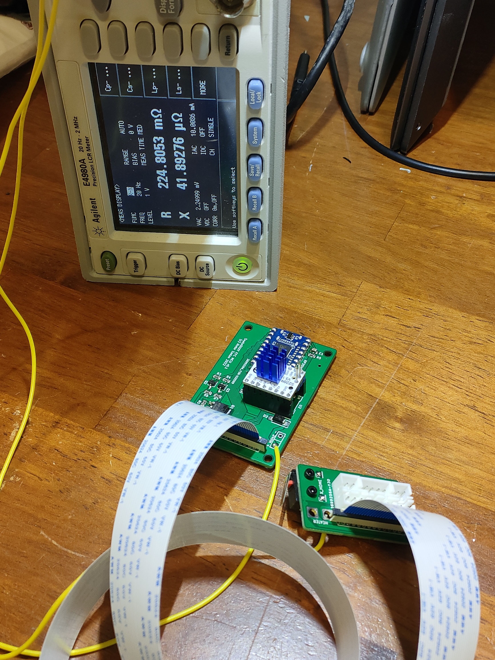
The heater is assumed to be a 24V 50W, using 4 FFC cable contacts in parallel. Approx. 500mA current flows per contact. Resistance of the heater wire is 266mΩ round trip including four screw terminals of 24V power supply and a 600mm FFC cable - which is measured by four-terminal-pair method. When a 24V 50W heater is used, there is a loss of about 1W including circuits, cable and contacts. (225mΩ for 53cm of lead wire, 157mΩ for 14cm of lead wire, so the loss in the circuit and FFC is 133mΩ. 266mΩ round trip. This resistance value includes the resistance of four contacts on the fixture)
| Qty | Value | Footprint | References |
|---|---|---|---|
| 5 | 4.7k | Resistor_SMD:R_0805_2012Metric_Pad1.20x1.40mm_HandSolder | R2, R5, R6, R7, R10 |
| 5 | LED_0805 | LED_SMD:LED_0805_2012Metric_Pad1.15x1.40mm_HandSolder | D3, D4, D5, D6, D7 |
| 4 | 100k | Resistor_SMD:R_0805_2012Metric_Pad1.20x1.40mm_HandSolder | R1, R3, R4, R8 |
| 3 | Jumper_3_Bridged12 | Jumper:SolderJumper-3_P1.3mm_Bridged12_RoundedPad1.0x1.5mm | JP1, JP2, JP3 |
| 2 | Conn_01x30 | ffc_connectors:ffc-30pin | J2, J8 |
| 2 | PL4009 | Package_TO_SOT_SMD:SOT-23_Handsoldering | Q2, Q3 |
| 1 | 100u/35V | Capacitor_SMD:CP_Elec_6.3x7.7 | C2 |
| 1 | 10k | Resistor_SMD:R_0805_2012Metric_Pad1.20x1.40mm_HandSolder | R9 |
| 1 | 10u | Capacitor_SMD:C_0805_2012Metric_Pad1.18x1.45mm_HandSolder | C1 |
| 1 | 1N5819WS | Diode_SMD:D_SOD-323_HandSoldering | D1 |
| 1 | KF128-5.08 | ffc_connectors:KF128-5.08 | J1 |
| 1 | Pico | RPi_Pico:RPi_Pico_SMD_TH | U1 |
| 1 | SMAJ28A | Diode_SMD:D_SMA_Handsoldering | D2 |
| 1 | WSF3085 | Package_TO_SOT_SMD:TO-252-2 | Q1 |
| 1 | dcdc_module | ffc_connectors:dcdc_24v_5v_module | U4 |
| 1 | max31865_module | ffc_connectors:adafruit_max31865_module | U3 |
| 1 | motor_driver | ffc_connectors:motor_driver | U2 |
The 32 most common of 36 parts.


wntrblm/jellyfish-and-starfish
Jellyfish and Starfish are control boards designed for use with the LumenPnP. Starfish controls the base of the machine including X & Y axes and pneumatics.

r-map/rmap
rete monitoraggio ambientale partecipativo documentation at https://doc.rmap.cc

hasenbanck/heteromycin
A 3D printer board using a powerfull STM32 MCU, TMC5160/TMC2160 driver and a Raspberry Pi or compatible SBC

hasenbanck/remram
32bit STM32F7 based 3D printing controller using TMC2130 stepper driver

OpenModbus/OM-64DO
A compact industrial-grade 64-channel Modbus RTU output module.

It measures 96.8 × 57.7 mm and has 2 copper layers, 1.6 mm thick.
36 parts, built around the 1N5819WS, KF128-5.0-8P, SMAJ28A and WSF3085. The full list of its parts is on this page, with links to each part's symbol and footprint where PCBKit's library has them.
From the sadaoikebe/SnakeOilXY-FFC repository on GitHub, at the commit this page was made from: the board is mcu2/mcu2.kicad_pcb and its schematic mcu2/mcu2.kicad_sch. PCBKit opens the board in the browser, with nothing to install.
Its repository publishes it under the GPL-3.0 licence: you may reuse it on that licence's terms (keep the author's notice, and for a copyleft licence share your changes alike).