6 layers100 × 50 mm
Archive
sikaxn/FRC-Custom-CAN-Sensor
If you are looking for IronMaple ESP32‐FRC‐devkit resources, please switch branch to dev-board.
92 parts12GPL-3.0

 W0rthlessS0ul/nRF24_jammer1k
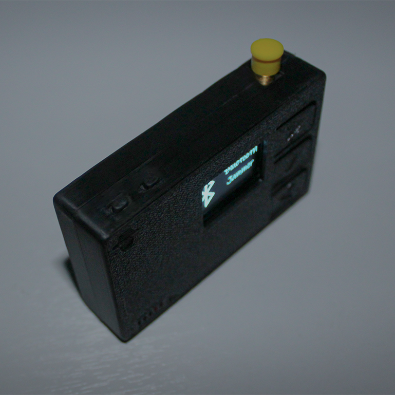
The nRF24 jammer is a powerful tool that requires an ESP32 and configurable numbers of NRF24 modules to assemble. It is designed to create interference, disrupting the normal operation of Bluetooth devices 🔊, BLE technology 📱, drones 🚁, Wi-Fi networks 📶 and Zigbee 📡. Additionally, it features a user-friendly web interface 🌐.
NRF24 jammer is an open-source printed circuit board by W0rthlessS0ul, from the W0rthlessS0ul/nRF24_jammer repository on GitHub, published under the MIT licence. It is a 2-layer board of 72 × 42 mm with 51 parts on 72 nets, routed with 326 tracks and 56 vias.
It is built around the CP2104EK, ESP32-WROOM-32D and LTC4054ES5-4.2#PBF, with the BC817 among its other parts. Its parts include 15 resistors, 13 capacitors, 6 ICs, 6 switches and 5 diodes. It belongs with the radio and wireless boards and the ESP32 boards of this library.


Welcome to the nRF24 Jammer repository! 🎉 Dive into the world of RF interference with this unique project based on the ESP32 and nRF24 technology.
This amazing jammer is built on the ESP32 architecture integrated with configurable numbers of nRF24 modules. With its extraordinary capabilities, you can effectively disrupt signals across different technologies including:
| Device | Repository URL |
|---|---|
| Flipper Zero | FZ_nRF24_jammer |
| LOLIN32 Lite | nRF24_jammer |
To bring this project to life, you will need the following components:
Any nRF24 modules are suitable, but CDEBYTE E01-2G4M27D is recommended
ESP-WROOM-32 ⚙️
16V capacitors rated at 100µF 🔋
128x32 or 128x64 OLED display 📺 (optional)
Tactile button 🔘 (optional)
| Preview | Author | Rev | Board README |
|---|---|---|---|
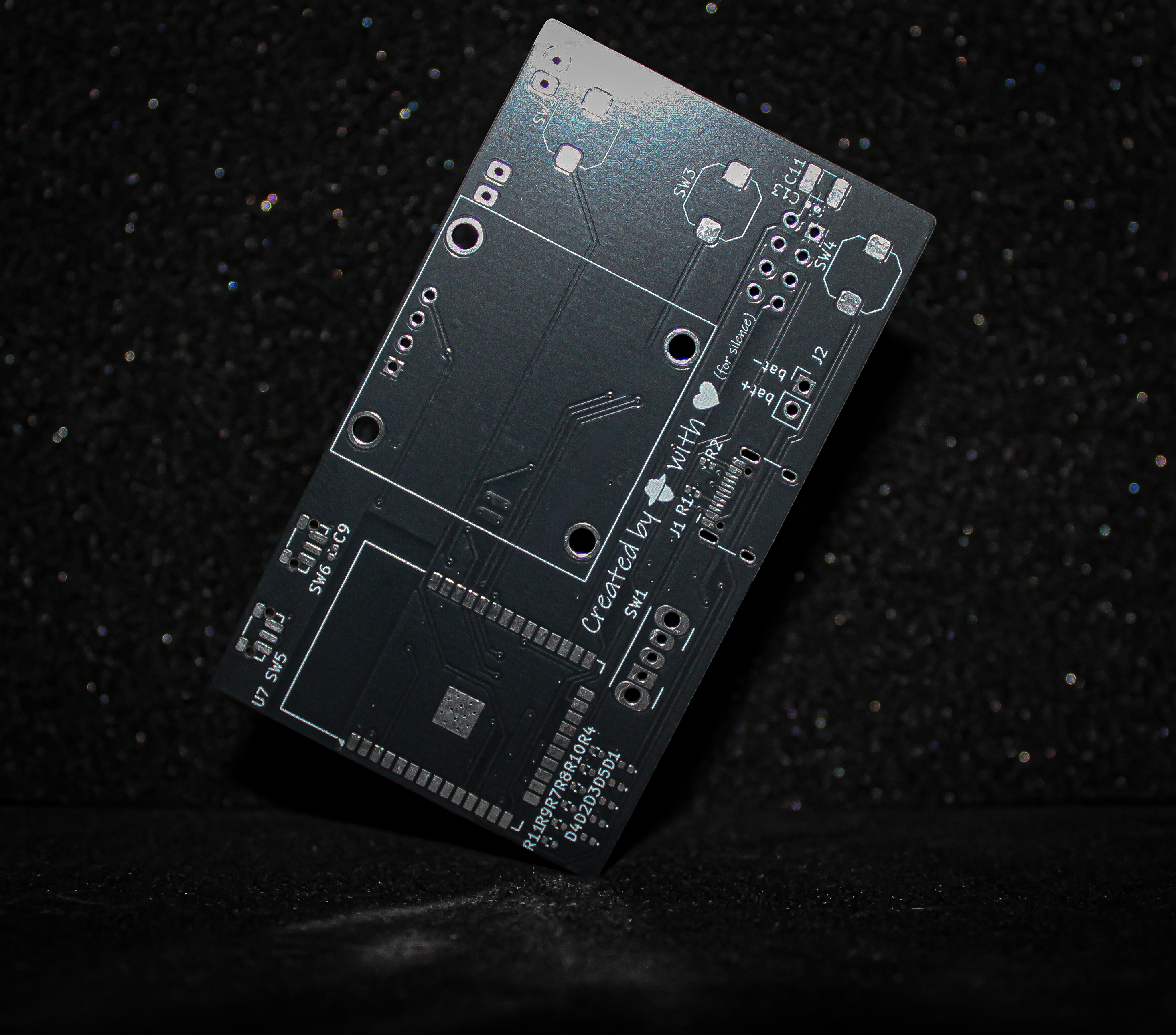 | @W0rthlessS0ul | v1.0.0 | README |
💡 Want to contribute your own PCB design?
If you feel confident in designing a high-quality PCB, feel free to submit your board via a Pull Request!
- Well-engineered and verified designs will be merged directly into the repository.
- If there are any doubts regarding layout quality, routing, or component selection, a thread will be opened in Discussions so the community can review, discuss, and vote on whether it should be added.
| Pin Name | ESP32 GPIO | Connection |
|---|---|---|
| VCC | 3.3V | (+) capacitor |
| GND | GND | (-) capacitor |
| CE | GPIO 16 | |
| CSN | GPIO 15 | |
| SCK | GPIO 14 | |
| MOSI | GPIO 13 | |
| MISO | GPIO 12 | |
| IRQ |
| Pin Name | ESP32 GPIO | Connection |
|---|---|---|
| VCC | 3.3V | (+) capacitor |
| GND | GND | (-) capacitor |
| CE | GPIO 18 | |
| CSN | GPIO 17 | |
| SCK | GPIO 14 | |
| MOSI | GPIO 13 | |
| MISO | GPIO 12 | |
| IRQ |
| Pin Name | ESP32 GPIO | Connection |
|---|---|---|
| VCC | 3.3V | (+) capacitor |
| GND | GND | (-) capacitor |
| CE | GPIO 23 | |
| CSN | GPIO 19 | |
| SCK | GPIO 14 | |
| MOSI | GPIO 13 | |
| MISO | GPIO 12 | |
| IRQ |
| Pin Name | ESP32 GPIO | Connection |
|---|---|---|
| VCC | 3.3V | (+) capacitor |
| GND | GND | (-) capacitor |
| CE | GPIO 5 | |
| CSN | GPIO 4 | |
| SCK | GPIO 14 | |
| MOSI | GPIO 13 | |
| MISO | GPIO 12 | |
| IRQ |
| Pin Name | ESP32 GPIO | Connection |
|---|---|---|
| VCC | 3.3V | (+) capacitor |
| GND | GND | (-) capacitor |
| CE | GPIO 33 | |
| CSN | GPIO 32 | |
| SCK | GPIO 14 | |
| MOSI | GPIO 13 | |
| MISO | GPIO 12 | |
| IRQ |
| Pin Name | ESP32 GPIO |
|---|---|
| VCC | 3.3V |
| GND | GND |
| SCL | GPIO 22 |
| SDA | GPIO 21 |
| Button Actions | ESP32 GPIO |
|---|---|
| OK | GPIO 25 |
| NEXT (Optional) | GPIO 26 |
| PREVIOUS (Optional) | GPIO 27 |
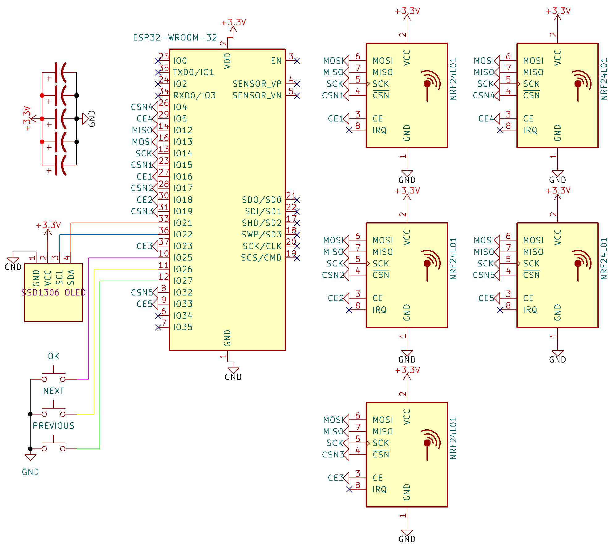
This section is addressed to contributors. If you are a regular user of the project, you can skip itproject_root/bin/[env_name]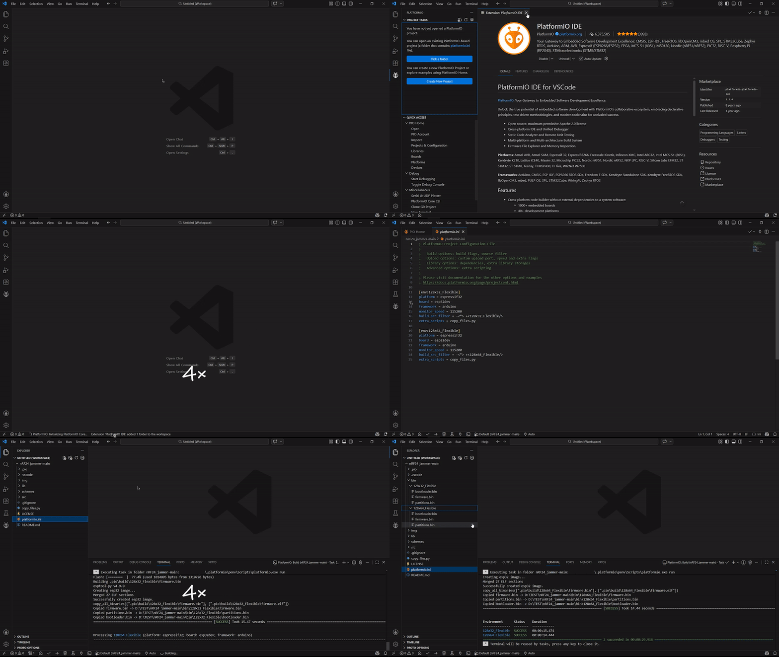
Follow these steps to flash the firmware:
| Address | File Name |
|---|---|
| 0x1000 | bootloader.bin |
| 0x8000 | partitions.bin |
| 0x10000 | firmware.bin |
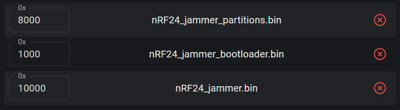
Follow these steps to flash the firmware:
⚠️️ make sure not to choose the bootloader or partitions files)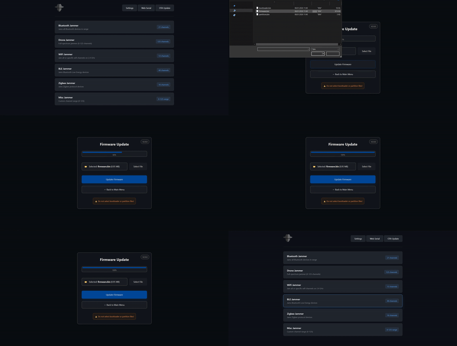
jammer using the password W0rthlessS0ul192.168.4.1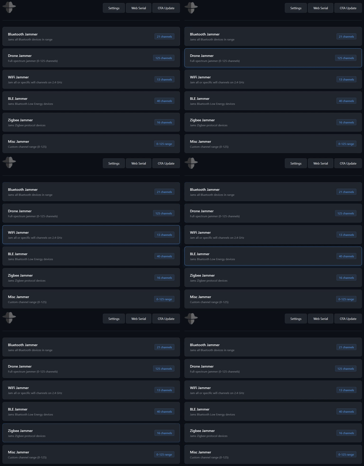
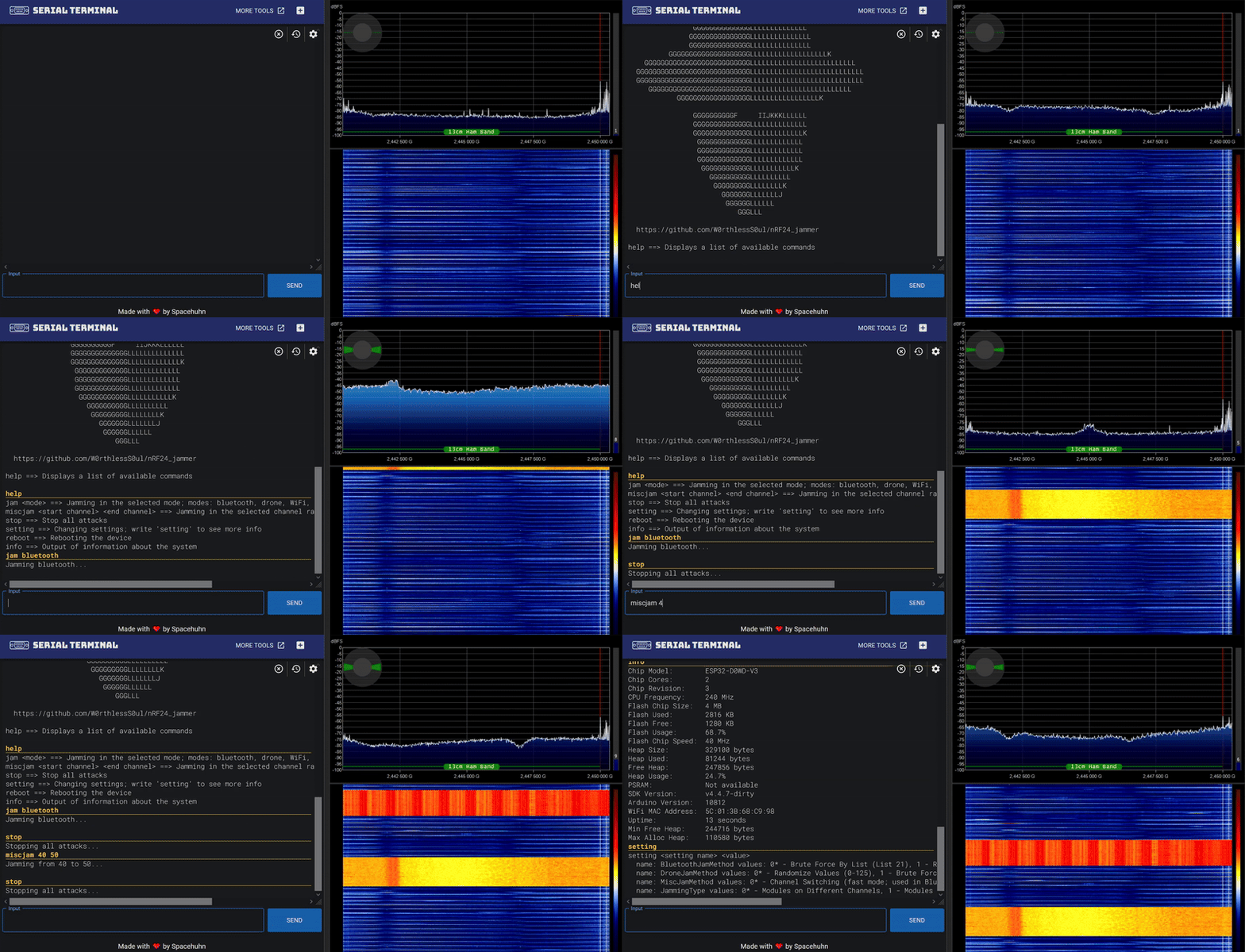
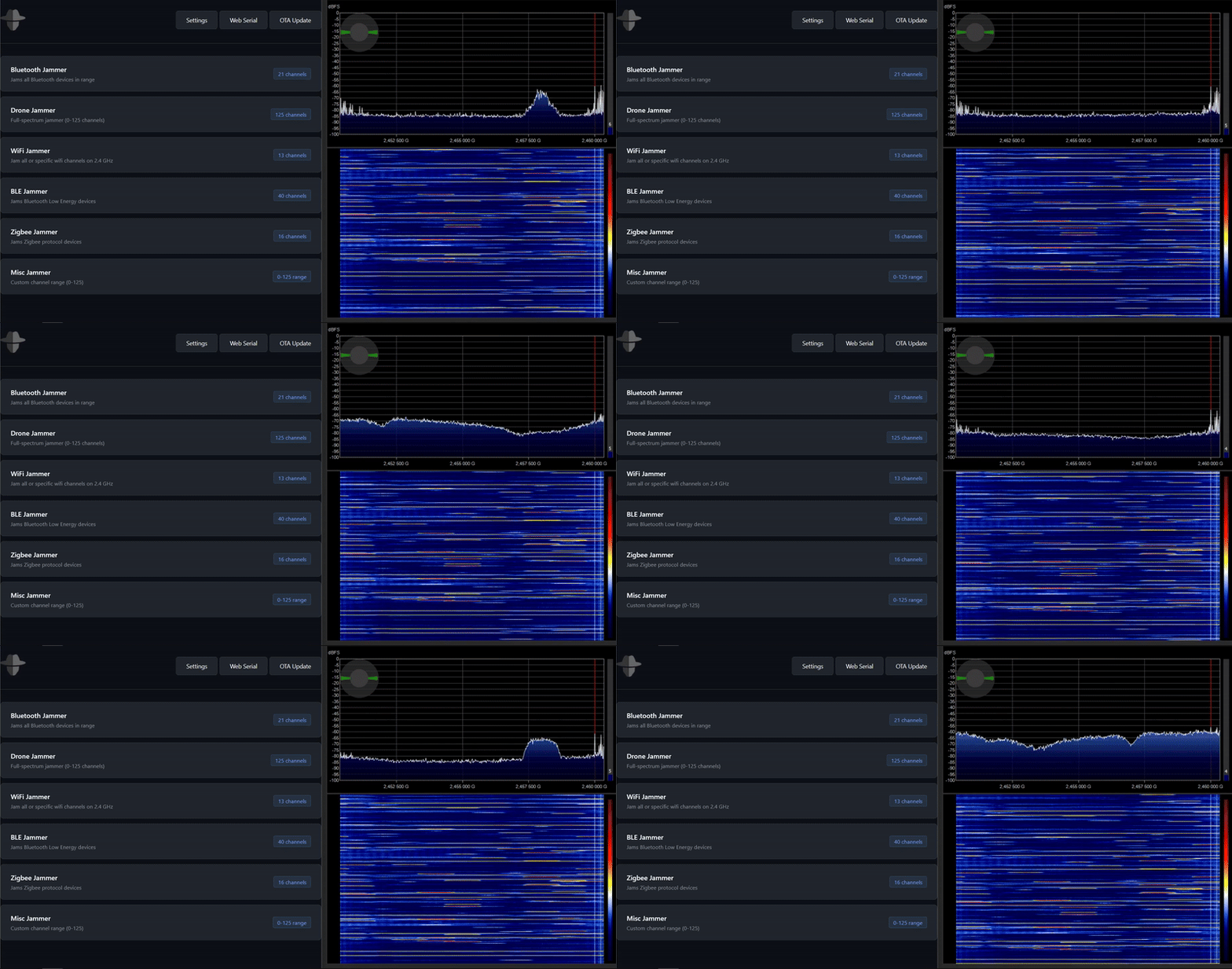
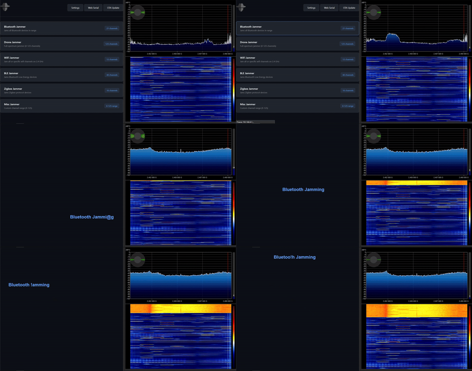
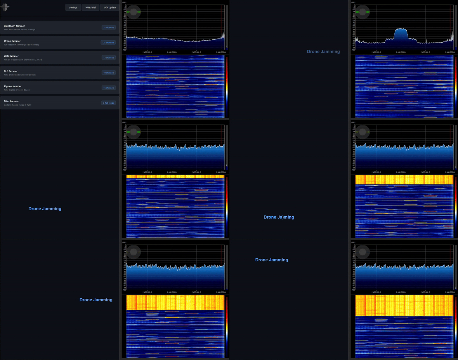
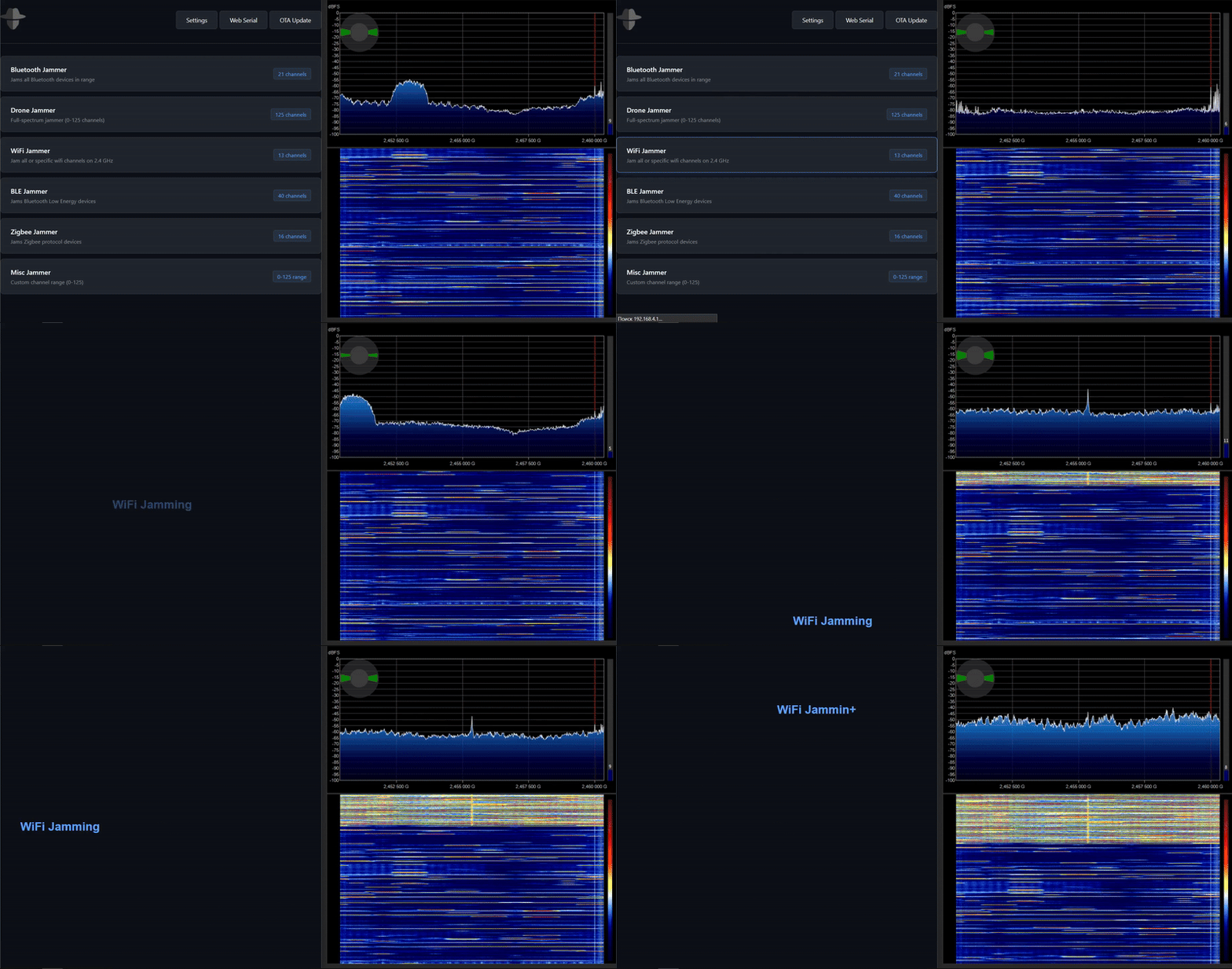
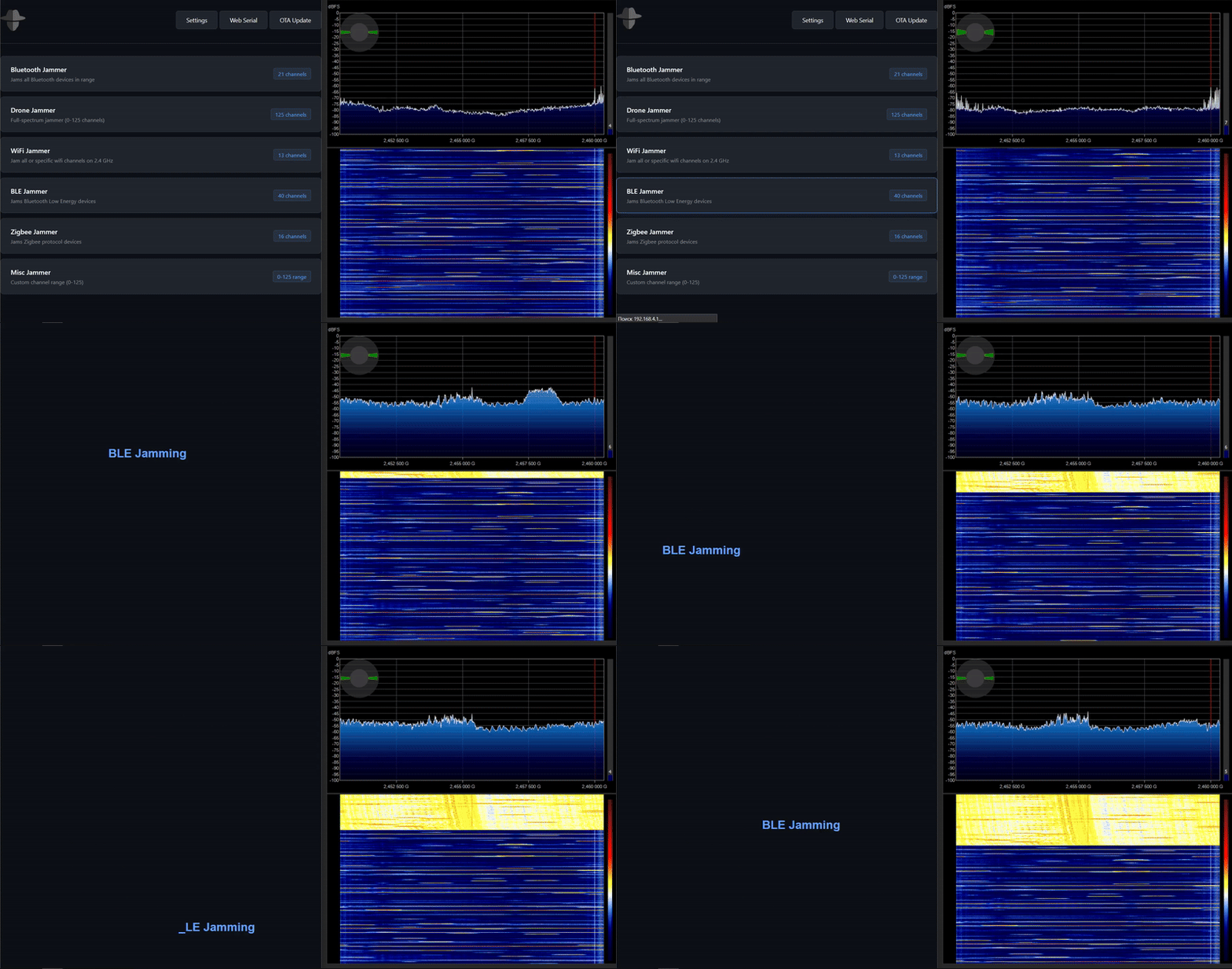
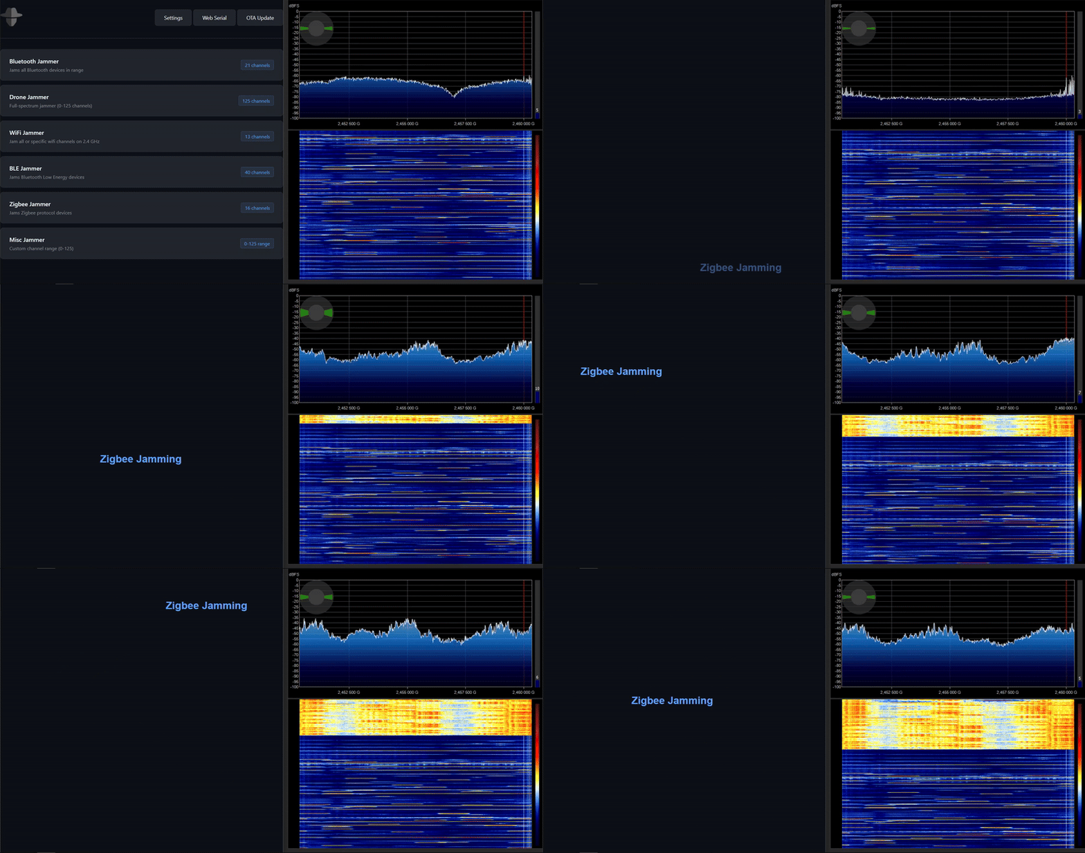
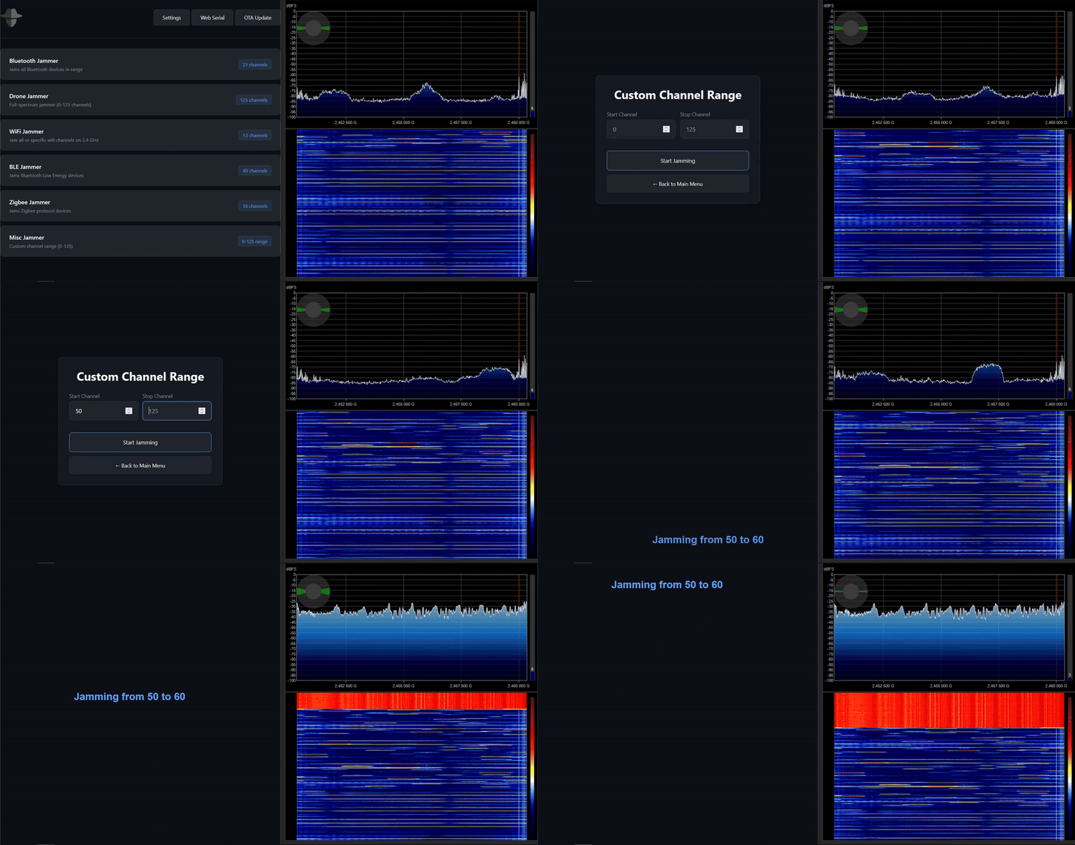
| Supporter | Contribution |
|---|---|
| @sergey2735 | 40.7 ADA |
If you find this project useful and want to support its ongoing development, consider starring the repository ⭐, following the author, or buying a cup of coffee to keep things fueled! ☕

|

|
| Coin / Network | Direct Wallet Address |
|---|---|
| 🟧 Bitcoin (BTC) | bc1qvul4mlxxw5h2hnt8knnxdrxuwgpf4styyk20tm |
| 🔷 Ethereum (ETH) | 0x5c54eAb2acFE1c6C866FB4b050d8B69CfB1138Af |
| ⚪ Litecoin (LTC) | LbdzCsYbxuD341raar6Cg1yKavaDq7fjuV |
| ⚫ Ripple (XRP) | rKLLPzoBGfqY3pAQPwTFPRYaWjpHSwHNDw |
| 🔵 Cardano (ADA) | addr1qyz2aku0ucmxqnl60lza23lkx2xha8zmxz9wqxnrtvpjysgy4mdcle3kvp8l5l7964rlvv5d06w9kvy2uqdxxkcryfqs7pajev |
| 🟡 Dogecoin (DOGE) | DBzAvD62yQUkP4Cb7C5LuFYQEierF3D3oG |
Every donation is greatly appreciated and directly contributes to the development, testing, and new hardware revisions of this project!
| Qty | Value | Footprint | References |
|---|---|---|---|
| 5 | 10k | Resistor_SMD:R_0402_1005Metric | R5, R6, R11, R13, R14 |
| 5 | 1k | Resistor_SMD:R_0402_1005Metric | R4, R7, R8, R9, R10 |
| 3 | 100nF | Capacitor_SMD:C_0402_1005Metric | C3, C12, C13 |
| 2 | 0.1uF | Capacitor_SMD:C_0402_1005Metric | C5, C8 |
| 2 | 100uF | Capacitor_SMD:C_1210_3225Metric | C10, C11 |
| 2 | 10uF | Capacitor_SMD:C_0805_2012Metric | C6, C7 |
| 2 | 1uF | Capacitor_SMD:C_0402_1005Metric | C4, C9 |
| 2 | 4.7k | Resistor_SMD:R_0402_1005Metric | R15, R16 |
| 2 | 4.7uF | Capacitor_SMD:C_0603_1608Metric | C1, C2 |
| 2 | 5.1k | Resistor_SMD:R_0402_1005Metric | R1, R2 |
| 2 | BC817 | Package_TO_SOT_SMD:SOT-23 | Q1, Q2 |
| 2 | Blue | Diode_SMD:D_0402_1005Metric | D1, D4 |
| 2 | LOGO | LOGO | G***, G*** |
| 2 | White | Diode_SMD:D_0402_1005Metric | D2, D3 |
| 1 | 2k | Resistor_SMD:R_0402_1005Metric | R3 |
| 1 | AP7361C-33E-13 | Package_TO_SOT_SMD:SOT-223-3_TabPin2 | U1 |
| 1 | Bat Connector | Connector_PinHeader_2.54mm:PinHeader_1x02_P2.54mm_Vertical | J2 |
| 1 | CDEBYTE E01-2G4M27D | nRF24_jammer:E01-2G4M27D | U5 |
| 1 | CP2104 | Package_DFN_QFN:QFN-24-1EP_4x4mm_P0.5mm_EP2.6x2.6mm | U2 |
| 1 | ESP32-WROOM-32D | RF_Module:ESP32-WROOM-32D | U7 |
| 1 | IO0 | Button_Switch_SMD:SW_Push_1P1T-MP_NO_Horizontal_Alps_SKRTLAE010 | SW5 |
| 1 | LTC4054ES5-4.2 | Package_TO_SOT_SMD:TSOT-23-5 | U3 |
| 1 | RESET | Button_Switch_SMD:SW_Push_1P1T-MP_NO_Horizontal_Alps_SKRTLAE010 | SW6 |
| 1 | Red | Diode_SMD:D_0402_1005Metric | D5 |
| 1 | SW_Nidec_CAS-120A1 | Button_Switch_THT:SW_Slide_SPDT_Angled_CK_OS102011MA1Q | SW1 |
| 1 | USB_C_Receptacle_USB2.0_16P | Connector_USB:USB_C_Receptacle_HCTL_HC-TYPE-C-16P-01A | J1 |
| 1 | next_btn | Button_Switch_SMD:SW_Push_1TS009xxxx-xxxx-xxxx_6x6x5mm | SW2 |
| 1 | ok_btn | Button_Switch_SMD:SW_Push_1TS009xxxx-xxxx-xxxx_6x6x5mm | SW3 |
| 1 | previous_btn | Button_Switch_SMD:SW_Push_1TS009xxxx-xxxx-xxxx_6x6x5mm | SW4 |
| 1 | ~ | nRF24_jammer:Display 0.96 breakout board | U6 |
sikaxn/FRC-Custom-CAN-Sensor
If you are looking for IronMaple ESP32‐FRC‐devkit resources, please switch branch to dev-board.

Habib-creater/ESP32-IoT-Monitoring-Control-Board
4-layer ESP32-based IoT monitoring and control board with environmental sensing, relay control, USB-C, and Qwiic expansion.


Tanmayeers/Projects
Specifications: 1. Operting Voltage: 9V 2. Operating Current: 200mA 3. Output Voltage Swing: 6.5V 4. 3dB - Bandwidth: 100 ± 10 Hz 5. Noise: 5.406mVrms

divquan/embedded-system-designs
This repository contains designs for embedded systems, including schematics, PCB layouts, and fabrication files. Ideal for learning and project inspiration.

jayatharshan12-design/ESP32-Custom-Development-Board-PCB-Design

Pyisoe-Thame/ESP_WROOM_32D
This repository contains files and designs created while following a YouTube tutorial on KiCad. The ESP-WROOM-32D is the same chip used in NodeMCU-32S development board.

YusufAlghoneimy/ESP32-PCB-Design
Youtube PCB reference: made by morten (https://www.youtube.com/watch?v=b-7bMl6fJio&t=8320s)
It measures 72 × 42 mm and has 2 copper layers, 1.6 mm thick.
51 parts, built around the CP2104EK, ESP32-WROOM-32D, LTC4054ES5-4.2#PBF and BC817. The full list of its parts is on this page, with links to each part's symbol and footprint where PCBKit's library has them.
From the W0rthlessS0ul/nRF24_jammer repository on GitHub, at the commit this page was made from: the board is PCB/W0rthlessS0ul/v1.0.0/kicad/nRF24_jammer.kicad_pcb and its schematic PCB/W0rthlessS0ul/v1.0.0/kicad/nRF24_jammer.kicad_sch. PCBKit opens the board in the browser, with nothing to install.
Its repository publishes it under the MIT licence: you may reuse it on that licence's terms (keep the author's notice, and for a copyleft licence share your changes alike).