4 layers60 × 60 mm
 QuadFlyController/Electronics
A high-performance, compact, 4-layer flight controller PCB engineered for quadcopters and small UAVs. Built around the STMicroelectronics STM32F411CEU6 MCU, featuring high-rate low-noise motion sensing, barometric…
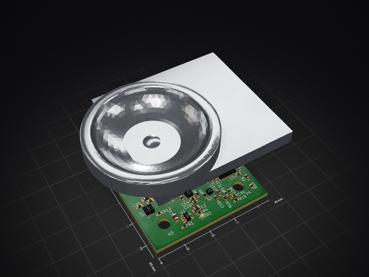
FlightController is an open-source printed circuit board by QuadFlyController, from the QuadFlyController/Electronics repository on GitHub, published under the MIT licence. It is a 4-layer board of 45 × 45 mm with 74 parts on 72 nets, routed with 617 tracks and 296 vias.
It is built around the BMP390, TPS62933DRL and AP2112K-3.3, with the ICM-42688-P, TPS2115ADRBR and USBLC6-2SC6 among its other parts. Its parts include 30 capacitors, 19 resistors, 7 ICs, 2 diodes and 2 connectors. It belongs with the robots and motor control boards and the STM32 boards of this library.


A high-performance, compact, 4-layer flight controller PCB engineered for quadcopters and small UAVs. Built around the STMicroelectronics STM32F411CEU6 MCU, featuring high-rate low-noise motion sensing, barometric altitude tracking, robust power management with dual-source automatic switching, and standard 30.5 mm × 30.5 mm mounting.
| Subsystem | Component | Description |
|---|---|---|
| Microcontroller (MCU) | STM32F411CEU6 | ARM Cortex-M4 @ 100 MHz, FPU, 512 KB Flash, 128 KB SRAM, external 25 MHz HSE oscillator |
| Inertial Measurement (IMU) | ICM-42688-P | High-precision 6-axis gyroscope & accelerometer on dedicated high-speed SPI bus with interrupt line |
| Barometer / Altimeter | BMP390 | Ultra-low noise barometric pressure sensor on SPI bus for altitude hold |
| Switching Regulator (Buck) | TPS62933 | High-efficiency 3A synchronous step-down converter providing stable +5V rail from battery |
| Linear Regulator (LDO) | AP2112K-3.3 | Ultra-low dropout, low-noise 600 mA 3.3V LDO for clean MCU and analog sensor rails |
| Power Path Switching | TPS2115A | Seamless automatic power multiplexer between USB VBUS (+5V) and internal Buck converter (+5V) |
| Transient Protection | SMBJ18A | Bidirectional TVS diode protection on battery input |
| USB Protection | USBLC6-2SC6 | Ultra-low capacitance ESD protection array on USB D+/D- lines |
| USB Interface | USB Type-C (16-pin) | Firmware flashing (DFU), telemetry, and configuration interface |
| ESC Interface | JST-SH 8-Pin (1.0 mm) | Standard 4-in-1 ESC connector (VBAT, GND, Motors 1–4, Current sensing) |
FlightController/CAD/FlightController.step for frame integration and enclosure design.SM08B-SRSS-TB)| Pin | Net Name | Function / Description |
|---|---|---|
| 1 | +BATT | Raw battery voltage input from ESC / PDB |
| 2 | GND | Power and signal ground return |
| 3 | CUR | Analog current sensing signal from ESC shunt sensor |
| 4 | M1 | Motor 1 PWM / DShot signal output (STM32 Timer channel) |
| 5 | M2 | Motor 2 PWM / DShot signal output (STM32 Timer channel) |
| 6 | M3 | Motor 3 PWM / DShot signal output (STM32 Timer channel) |
| 7 | M4 | Motor 4 PWM / DShot signal output (STM32 Timer channel) |
| 8 | GND | Ground return |
D1: Power indicatorD2: User / Status LED (connected to STM32 GPIO)Electronics/
├── .gitignore # Git ignore configuration
├── LICENSE # License file
├── README.md # Hardware documentation
├── FlightController_Schematic.pdf # Exported full schematic PDF
│
└── FlightController/ # KiCad 10 Project Directory
├── FlightController.kicad_pro # KiCad project file
├── FlightController.kicad_pcb # KiCad 4-layer PCB layout
├── FlightController.kicad_sch # Root schematic sheet
├── MCU.kicad_sch # STM32F411CEU6 microcontroller sheet
├── IMU.kicad_sch # ICM-42688-P & BMP390 sensor sheet
├── PowerManagement.kicad_sch # Power rails, buck, LDO, & USB sheet
├── fp-lib-table # Footprint library table
├── sym-lib-table # Symbol library table
├── fabrication-toolkit-options.json # Production generation settings
│
├── CAD/ # 3D Mechanical Models
│ └── FlightController.step # Complete 3D STEP assembly of the PCB
│
└── production/ # Manufacturing & Assembly Files
├── FlightController.zip # Gerbers & Drill archive (RS-274X / Excellon)
├── bom.csv # Bill of Materials (with LCSC part numbers)
├── positions.csv # Pick-and-Place (CPL) centroid coordinates
├── designators.csv # Component designator mapping
└── netlist.ipc # IPC-D-356 netlist for bare-board testingThe files in FlightController/production/ are pre-configured and formatted for rapid quoting and ordering with PCB manufacturers (such as JLCPCB, PCBWay, etc.):
FlightController/production/FlightController.zip.FlightController/production/bom.csv (includes pre-matched LCSC part numbers for automated component sourcing).FlightController/production/positions.csv.FlightController/production/netlist.ipc is provided for automated flying-probe netlist verification.FlightController/FlightController.kicad_pro.FlightController_Schematic.pdf.| Qty | Value | Footprint | References |
|---|---|---|---|
| 13 | 0.1μF X7R | Capacitor_SMD:C_0603_1608Metric_Pad1.08x0.95mm_HandSolder | C4, C7, C8, C9, C12, C13, C14, C17, C18, C21, C27, C29, C30 |
| 6 | 10kΩ | PCM_JLCPCB:R_0603 | R5, R6, R7, R8, R13, R16 |
| 4 | MountingHole | MountingHole:MountingHole_4.3mm_M4 | H1, H2, H3, H4 |
| 3 | 10μF X7R | Capacitor_SMD:C_0805_2012Metric_Pad1.18x1.45mm_HandSolder | C1, C2, C28 |
| 3 | 5.1kΩ | PCM_JLCPCB:R_0603 | R2, R3, R4 |
| 2 | 10μF X7R 50V | Capacitor_SMD:C_1206_3216Metric_Pad1.33x1.80mm_HandSolder | C19, C20 |
| 2 | 14pF C0G | Capacitor_SMD:C_0402_1005Metric_Pad0.74x0.62mm_HandSolder | C10, C11 |
| 2 | 1kΩ | PCM_JLCPCB:R_0603 | R17, R19 |
| 2 | 22μF X5R 35V | Capacitor_SMD:C_1206_3216Metric_Pad1.33x1.80mm_HandSolder | C24, C25 |
| 2 | 4.7μF X7R | Capacitor_SMD:C_0603_1608Metric_Pad1.08x0.95mm_HandSolder | C5, C6 |
| 2 | LED | LED_SMD:LED_0603_1608Metric | D1, D2 |
| 1 | 0.1μF X7R 16V | Capacitor_SMD:C_0603_1608Metric_Pad1.08x0.95mm_HandSolder | C23 |
| 1 | 0.1μF X7R 35V | Capacitor_SMD:C_0603_1608Metric_Pad1.08x0.95mm_HandSolder | C26 |
| 1 | 1.5kΩ | PCM_JLCPCB:R_0603 | R18 |
| 1 | 10.2k | Resistor_SMD:R_0603_1608Metric_Pad0.98x0.95mm_HandSolder | R9 |
| 1 | 100kΩ | PCM_JLCPCB:R_0603 | R1 |
| 1 | 10nF X7R | Capacitor_SMD:C_0603_1608Metric_Pad1.08x0.95mm_HandSolder | C16 |
| 1 | 10Ω | PCM_JLCPCB:R_0603 | R11 |
| 1 | 1μF X7R | Capacitor_SMD:C_0603_1608Metric_Pad1.08x0.95mm_HandSolder | C3 |
| 1 | 2.2μF X7R | Capacitor_SMD:C_0603_1608Metric_Pad1.08x0.95mm_HandSolder | C15 |
| 1 | 200k | Resistor_SMD:R_1206_3216Metric_Pad1.30x1.75mm_HandSolder | R15 |
| 1 | 25MHz_GND24 | CRYSTAL-SMD_4P-L3.2-W2.5-BL:CRYSTAL-SMD_4P-L3.2-W2.5-BL | Y1 |
| 1 | 33nF X7R | Capacitor_SMD:C_0603_1608Metric_Pad1.08x0.95mm_HandSolder | C22 |
| 1 | 400 | Resistor_SMD:R_0603_1608Metric_Pad0.98x0.95mm_HandSolder | R12 |
| 1 | 510k | Resistor_SMD:R_1206_3216Metric_Pad1.30x1.75mm_HandSolder | R14 |
| 1 | 53.6k | Resistor_SMD:R_0603_1608Metric_Pad0.98x0.95mm_HandSolder | R10 |
| 1 | 5V | TestPoint:TestPoint_Pad_3.0x3.0mm | TP3 |
| 1 | 74439346068 | 74439346068:74439346068 | L1 |
| 1 | AP2112K-3.3 | Package_TO_SOT_SMD:SOT-23-5_HandSoldering | U1 |
| 1 | BMP390 | BMP390:BMP390 | U5 |
| 1 | Conn_01x03_Pin | Connector_PinHeader_1.00mm:PinHeader_1x03_P1.00mm_Vertical | J1 |
| 1 | GND | TestPoint:TestPoint_Pad_3.0x3.0mm | TP4 |
| 1 | ICM-42688-P | ICM-42688-P:ICM-42688-P-M | U4 |
| 1 | LOGO | LOGO | G*** |
| 1 | RX | TestPoint:TestPoint_Pad_3.0x3.0mm | TP2 |
| 1 | SM08B-SRSS-TBLFSN | XY-SM08B-SRSS-TB:XY-SM08B-SRSS-TB | J3 |
| 1 | SMBJ18A | SMBJ18A:SMBJ18A | CR1 |
| 1 | STM32F411CEUx | Package_DFN_QFN:QFN-48-1EP_7x7mm_P0.5mm_EP5.6x5.6mm | U3 |
| 1 | SolderJumper_2_Open | Jumper:SolderJumper-2_P1.3mm_Open_Pad1.0x1.5mm | JP1 |
| 1 | TPS2115ADRBR | TPS2115ADRBR:TPS2115ADRBR | U7 |
| 1 | TPS62933 | Package_TO_SOT_SMD:SOT-583-8 | U6 |
| 1 | TX | TestPoint:TestPoint_Pad_3.0x3.0mm | TP1 |
| 1 | USB-TYPE-C-018 | USB-TYPE-C-018:USB-C_SMD-TYPE-C-31-M-12 | USB1 |
| 1 | USBLC6-2SC6 | Package_TO_SOT_SMD:SOT-23-6_Handsoldering | U2 |
It measures 45 × 45 mm and has 4 copper layers, 1.62 mm thick.
74 parts, built around the BMP390, TPS62933DRL, AP2112K-3.3 and ICM-42688-P. The full list of its parts is on this page, with links to each part's symbol and footprint where PCBKit's library has them.
From the QuadFlyController/Electronics repository on GitHub, at the commit this page was made from: the board is FlightController/FlightController.kicad_pcb and its schematic FlightController/FlightController.kicad_sch. PCBKit opens the board in the browser, with nothing to install.
Its repository publishes it under the MIT licence: you may reuse it on that licence's terms (keep the author's notice, and for a copyleft licence share your changes alike).

Stab-Rabbit-coding/Serenity-UAV
A functional, security conscious, Unmanned Aerial Vehicle based on the Firefly Class spacecraft Serenity from the 2002 show..

robocore-labs/link101-hardware
link101 is a multi-protocol USB interface board. One Type-C cable gives you CAN-FD, RS485, Dynamixel, Feetech, UART, I2C, and MIT Cheetah-protocol ports, all as stable Linux devices.

sbbxiii/The-Eagle
The Eagle: Custom STM32F405 4-Layer Autonomous Avionics Flight Controller PCB

hpvdt/falcon_motherboard
Firmware and hardware designs for the Falcon motherboard

sarahjuma1/STM32-Flight-Controller-PCB-Copy
4-layer STM32F405-based flight controller PCB featuring IMU, barometer, SPI flash, USB-C, and ESC interfaces.

ThorbenH/ba-thesis-project
This git project is dedicated to a prototype implementation that attempts to track and evaluate the motion of a barbell in the gym.

ukinori/flightcontroller
STM32H743 VTOL/fixed-wing flight-controller hardware in KiCad 10: routed 4-layer PCB, schematics, BOM notes, connector pinouts and verification reports. Experimental prototype; PX4 port planned.