6 layers128 × 91 mm
 ukinori/flightcontroller
STM32H743 VTOL/fixed-wing flight-controller hardware in KiCad 10: routed 4-layer PCB, schematics, BOM notes, connector pinouts and verification reports. Experimental prototype; PX4 port planned.
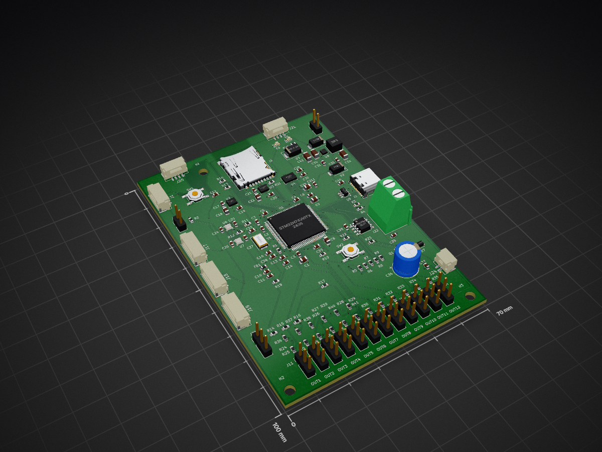
Flightcontroller is an open-source printed circuit board by ukinori, from the ukinori/flightcontroller repository on GitHub. It is a 4-layer board of 70 × 100 mm with 132 parts on 141 nets, routed with 3,528 tracks and 249 vias.
It is built around the BMP390, MB85RS64PNF-G-JNE1 and TPS62162DSGR, with the DM3AT-SF-PEJM5, ICM-42688-P and BMI088 among its other parts. Its parts include 42 capacitors, 41 resistors, 24 connectors, 9 ICs and 6 diodes. It belongs with the robots and motor control boards and the STM32 boards of this library.


Custom four-layer flight-controller hardware for VTOL and fixed-wing aircraft, designed in KiCad 10 around the STM32H743VITx. The intended aircraft configuration is four lift motors, one cruise motor and up to five servos. The hardware has twelve output connectors, allowing spare channels.
Status: routed hardware prototype. PX4 integration is planned; this repository does not contain a completed PX4 board port, bootloader or flight-tested firmware. The board has not been electrically or flight qualified. Design-rule checks do not establish functional or flight safety.
Hardware inspection guide · Board review and bring-up checklist
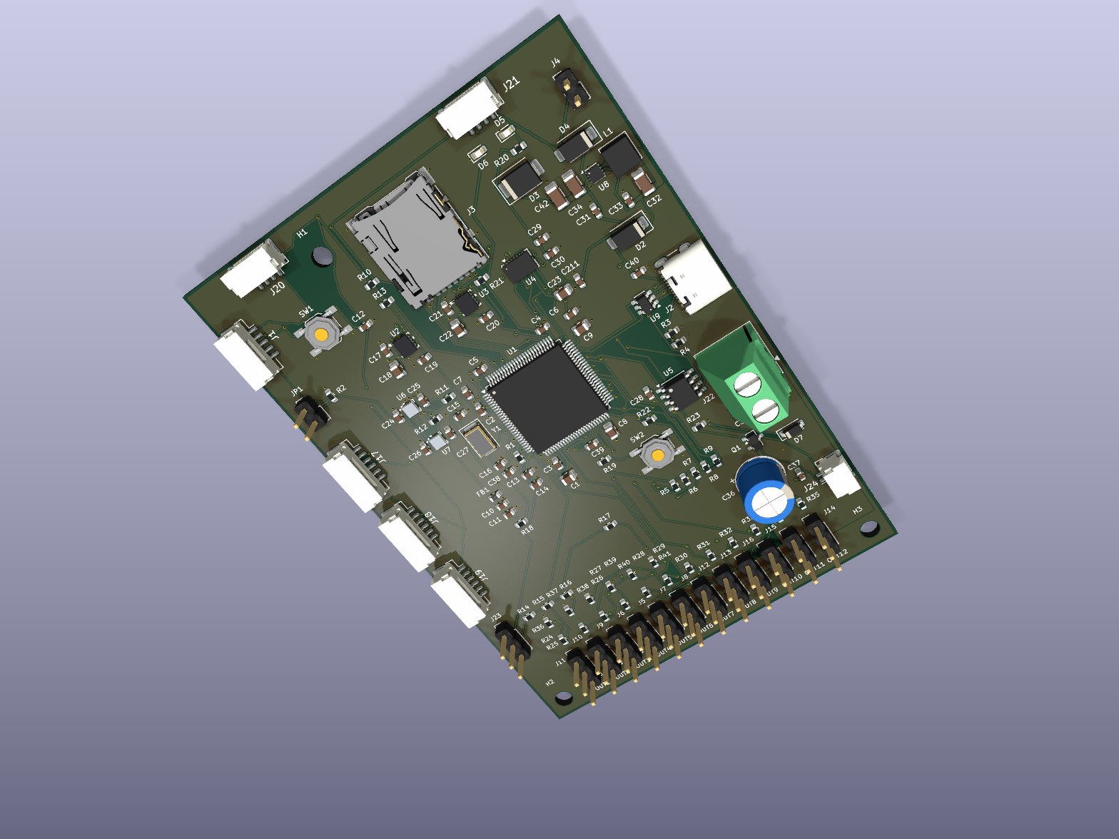
Current KiCad 3D rendering. Sensor bodies include nominal package envelopes; see 3D model notes.
Exact component references, values, connections and footprints are defined by the KiCad sources. The BOM CSV files cover footprint assignments and selected power/crystal/decoupling parts; they are not a fully qualified purchasing BOM.
git clone https://github.com/ukinori/flightcontroller.git.${KIPRJMOD} paths.models/ beside the project and install the standard KiCad 3D model libraries.The root schematic contains MCU, power and interface sheets. The MCU sheet is currently named untitled.kicad_sch; this file is required by the hierarchy.
The servo distribution has a provisional 10 A aggregate design target, not a verified current rating. Select actual servos, calculate combined stall/peak current and validate the BEC, connector, wiring, copper thickness, voltage drop and temperature rise before use. Servos/ESCs must accept the controller's signal levels.
Every output header uses pin 1 for signal and pin 3 for GND. Pin 2 is unconnected on OUT1–OUT6; on OUT7–OUT12 it is VCC_SERVO.
The intended allocation is OUT1–OUT5 for five DShot ESCs, OUT7–OUT11 for five PWM servos, and OUT6/OUT12 as spares. Timer, DMA and output-mode support still need implementation and testing in a dedicated PX4 board port.
See the JST-GH wiring guide and connector BOM before making cables.
J4, J22, OUT1–OUT12, USB-C and microSD remain unchanged. J23 remains a power-measurement exception because the GH voltage rating is 50 V, below a fully charged 12S pack at 50.4 V. RC and SWD retain custom pinouts and are not interchangeable with Pixhawk RC/debug cables.
TX/RX names refer to the controller. Check the external device's voltage levels and cable pinout; matching connector size does not establish compatibility.
Review the final manufacturer's stack-up, signal return paths, USB/SDMMC routing, converter layout and servo-current distribution before fabrication. Current design minima include 0.15 mm tracks/clearances and 0.20 mm via drills; these require manufacturer confirmation.
KiCad CLI 10.0.4 checks on the publication snapshot:
The existing project settings ignore some checks. DRC ignores missing_courtyard, track_not_centered_on_via, tuning_profile_track_geometries, footprint_filters_mismatch and footprint_type_mismatch. ERC ignores single_global_label, four_way_junction, simulation_model_issue and footprint_filter. The JSON reports retain this information. Zero findings apply to this configured check set.
Current JST-GH revision reports are verification/ERC-2026-10-22.json and verification/DRC-2026-10-22.json. All 480 schematic pin assignments match the board; the 125 unchanged footprints retain their positions. No check severities were relaxed for this revision. Older reports, images and routing notes are retained as historical records.
FlightController.pretty/, FlightController.kicad_sym — project-local CAD libraries.verification/ — ERC, DRC and net-assignment checks, with dated historical reports.images/flightcontroller-3d.png — current board rendering.models/ — nominal ICM42688 and BMP390 package envelopes used by KiCad 3D Viewer.README-JST-GH.md, JST-GH-CONNECTORS.csv — current port wiring and connector parts.docs/PROJECT-RU.md — English hardware inspection and bring-up guide. Legacy filenames containing RU are retained for existing links; all current documentation is in English.meshtransciever/ — a separate, unfinished radio/mesh hardware project included from the source folder. Its PCB is a placeholder; it is not part of the flight-controller verification results.Editor history, restore backups, lock files and machine-specific UI state are excluded. The published project uses a portable symbol-library table with project-relative paths.
No project-wide license has been added. Existing third-party library notices are retained in their source files.
| Qty | Value | Footprint | References |
|---|---|---|---|
| 24 | 100n | Capacitor_SMD:C_0603_1608Metric | C2, C3, C10, C12, C13, C17, C21, C24, C25, C26, C27, C28, C29, C30, C31, C211 +8 |
| 12 | 100 | Resistor_SMD:R_0603_1608Metric | R24, R25, R26, R27, R28, R29, R30, R31, R32, R33, R34, R35 |
| 12 | Conn_01x03 | Connector_PinHeader_2.54mm:PinHeader_1x03_P2.54mm_Vertical | J5, J6, J7, J8, J9, J10, J11, J12, J13, J14, J15, J16 |
| 8 | 10k | Resistor_SMD:R_0603_1608Metric | R2, R19, R36, R37, R38, R39, R40, R41 |
| 5 | 47k | Resistor_SMD:R_0603_1608Metric | R5, R6, R7, R8, R9 |
| 4 | 1k | Resistor_SMD:R_0603_1608Metric | R17, R18, R20, R21 |
| 4 | 4.7k | Resistor_SMD:R_0603_1608Metric | R10, R11, R12, R13 |
| 3 | 1mu | Capacitor_SMD:C_0603_1608Metric | C7, C11, C14 |
| 3 | M3 | MountingHole:MountingHole_3.2mm_M3 | H1, H2, H3 |
| 2 | 10nF | Capacitor_SMD:C_0603_1608Metric | C19, C20 |
| 2 | 10u | Capacitor_SMD:C_1206_3216Metric | C34, C42 |
| 2 | 18p | Capacitor_SMD:C_0603_1608Metric | C15, C16 |
| 2 | 2.2mu | Capacitor_SMD:C_0805_2012Metric | C8, C9 |
| 2 | 2.2u | Capacitor_SMD:C_0805_2012Metric | C18, C22 |
| 2 | 5.1k | Resistor_SMD:R_0603_1608Metric | R3, R4 |
| 2 | 91k 1% | Resistor_SMD:R_0603_1608Metric | R14, R15 |
| 2 | BMP390 | FlightController:10LGA_2X2X0p75_BOS | U6, U7 |
| 2 | ICM-42688-P | FlightController:LGA14_2P5X3X0P91_TDK | U2, U3 |
| 2 | SS14 | Diode_SMD:D_SMA | D2, D4 |
| 1 | 100k | Resistor_SMD:R_0603_1608Metric | R23 |
| 1 | 10k 1% | Resistor_SMD:R_0603_1608Metric | R16 |
| 1 | 10u | Capacitor_SMD:C_0805_2012Metric | C23 |
| 1 | 10u | Capacitor_SMD:C_0603_1608Metric | C35 |
| 1 | 1N4148W | Diode_SMD:D_SOD-123 | D7 |
| 1 | 2.2k | Resistor_SMD:R_0603_1608Metric | R22 |
| 1 | 22u | Capacitor_SMD:C_1206_3216Metric | C32 |
| 1 | 3.3u | Inductor_SMD:L_Coilcraft_XAL4030-XXX | L1 |
| 1 | 47 | Resistor_SMD:R_0603_1608Metric | R1 |
| 1 | 470u 16V | Capacitor_THT:CP_Radial_D8.0mm_P3.50mm | C36 |
| 1 | 4mu7 | Capacitor_SMD:C_0805_2012Metric | C1 |
| 1 | 5V_REGULATED_INPUT | Connector_PinHeader_2.54mm:PinHeader_1x02_P2.54mm_Vertical | J4 |
| 1 | 8MHz | Crystal:Crystal_SMD_Abracon_ABM3-2Pin_5.0x3.2mm | Y1 |
| 1 | AIRSPEED_I2C4_5V | Connector_JST:JST_GH_SM04B-GHS-TB_1x04-1MP_P1.25mm_Horizontal | J21 |
| 1 | BATTERY_SENSE_ONLY | Connector_PinHeader_2.54mm:PinHeader_1x03_P2.54mm_Vertical | J23 |
| 1 | BMI088 | Package_LGA:Bosch_LGA-16_4.5x3mm_P0.5mm_LayoutBorder7x1y_ClockwisePinNumbering | U4 |
| 1 | BUZZER_5V_20mA_MAX | Connector_JST:JST_GH_SM02B-GHS-TB_1x02-1MP_P1.25mm_Horizontal | J24 |
| 1 | COMPASS_I2C4_5V | Connector_JST:JST_GH_SM04B-GHS-TB_1x04-1MP_P1.25mm_Horizontal | J20 |
| 1 | FerriteBead | Inductor_SMD:L_0603_1608Metric | FB1 |
| 1 | GPS_PIXHAWK_GPS2 | Connector_JST:JST_GH_SM06B-GHS-TB_1x06-1MP_P1.25mm_Horizontal | J18 |
| 1 | Jumper_2_Open | Connector_PinHeader_2.54mm:PinHeader_1x02_P2.54mm_Vertical | JP1 |
| 1 | MB85RS64 | Package_SO:SOIC-8_3.9x4.9mm_P1.27mm | U5 |
| 1 | MMBT3904 | Package_TO_SOT_SMD:SOT-23 | Q1 |
| 1 | Micro_SD_Card | Connector_Card:microSD_HC_Hirose_DM3AT-SF-PEJM5 | J3 |
| 1 | POWER_GREEN | LED_SMD:LED_0603_1608Metric | D5 |
| 1 | RC_UART_GH6_NO_FLOW | Connector_JST:JST_GH_SM06B-GHS-TB_1x06-1MP_P1.25mm_Horizontal | J17 |
| 1 | RESET | Button_Switch_SMD:SW_SPST_TL3342 | SW1 |
| 1 | SAFETY | Button_Switch_SMD:SW_SPST_TL3342 | SW2 |
| 1 | SERVO_BEC_6V_INPUT | TerminalBlock_Phoenix:TerminalBlock_Phoenix_MKDS-1,5-2-5.08_1x02_P5.08mm_Horizontal | J22 |
| 1 | SMBJ5.0A | Diode_SMD:D_SMB | D3 |
| 1 | STATUS_GREEN | LED_SMD:LED_0603_1608Metric | D6 |
| 1 | STM32H743VITx | Package_QFP:LQFP-100_14x14mm_P0.5mm | U1 |
| 1 | SWD_CUSTOM_GH5 | Connector_JST:JST_GH_SM05B-GHS-TB_1x05-1MP_P1.25mm_Horizontal | J1 |
| 1 | TELEM_GH6_NO_FLOW | Connector_JST:JST_GH_SM06B-GHS-TB_1x06-1MP_P1.25mm_Horizontal | J19 |
| 1 | TPS62162DSG | Package_SON:WSON-8-1EP_2x2mm_P0.5mm_EP0.9x1.6mm_ThermalVias | U8 |
| 1 | USBLC6-2SC6 | Package_TO_SOT_SMD:SOT-23-6 | U9 |
| 1 | USB_C_Receptacle_USB2.0_14P | Connector_USB:USB_C_Receptacle_GCT_USB4105-xx-A_16P_TopMnt_Horizontal | J2 |
It measures 70 × 100 mm and has 4 copper layers, 1.6 mm thick.
132 parts, built around the BMP390, MB85RS64PNF-G-JNE1, TPS62162DSGR and DM3AT-SF-PEJM5. The full list of its parts is on this page, with links to each part's symbol and footprint where PCBKit's library has them.
From the ukinori/flightcontroller repository on GitHub, at the commit this page was made from: the board is flightcontroller.kicad_pcb and its schematic flightcontroller.kicad_sch. PCBKit opens the board in the browser, with nothing to install.
Its repository states no licence, so its author keeps all rights: ask ukinori before reusing the design.

nakul-biovaco/ESP32-Custom-PCB
Production-Grade 4-Layer ESP32-WROOM-32E Custom Development Board with Synchronous Buck Converter & Type-C (KiCad 8/10, JLCPCB PCBA Ready)

ThorbenH/ba-thesis-project
This git project is dedicated to a prototype implementation that attempts to track and evaluate the motion of a barbell in the gym.

felixznr/ALBERT
Albert I was a rhesus macaque monkey and the first mammal launched on a rocket (V-2 Rocket "Blossom No. 3") on June 18, 1948.

ChladpavPy/Aero-Zero
I started this project, because I wanted to build fully autonomous ai drone. When I looked at the flight controllers available on the market, they were full of hardware that I just do not need or just that I could not…

ErdemA33/stm32f405-flight-controller
Open-source ArduPilot-compatible flight controller for fixed-wing UAVs. STM32F405, 4-layer KiCad design, built in 5 modular stages.


hpvdt/falcon_motherboard
Firmware and hardware designs for the Falcon motherboard