6 layers56.7 × 54.7 mm
Better md80
darshp848/bldc-controller-60v
60 V, 20 A / 80 A peak BLDC motor controller that fits the MD80 v3.0 mounting. KiCad 10, 6 layers.
144 parts1

 Prinsessen/canfd-mc-hardware
CANFD-MC: a 55 x 32 mm, 4-layer CAN board for a motorcycle (KiCad, JLCPCB-ready) - ESP32-S3 + MCP2518FD CAN FD + TCAN332G, 6-40 V load-dump-proof input, ~10 uA standby on the battery. Drop-in replacement for the LilyGO T-2CANFD in the Indian Thunder Stroke CAN bus project; same pin map, firmware unchanged.
Canfd mc is an open-source printed circuit board by Prinsessen, from the Prinsessen/canfd-mc-hardware repository on GitHub, published under the MIT licence. It is a 4-layer board of 55 × 32 mm with 51 parts on 60 nets, routed with 193 tracks and 68 vias.
It is built around the ESP32-S3-WROOM-1U-N16R8, LM5164DDAR and MCP2518FDT-E/SL-HX, with the DLW43SH101XK2L, PESD2CAN and SMBJ24CA among its other parts. Its parts include 17 capacitors, 9 resistors, 4 ICs, 4 connectors and 3 diodes. It belongs with the interfaces and adapters and power boards and the ESP32 boards of this library.


A 55 × 32 mm, 4-layer board that replaces the LilyGO T-2CANFD in the
indian-thunderstroke-canbus
project: ESP32-S3-WROOM-1U + MCP2518FD + TCAN332G, fed from the bike's
permanent 12 V through an LM5164 buck. Same pin map as the LilyGO board, so the
firmware runs unchanged (sniffer-t2can environment).
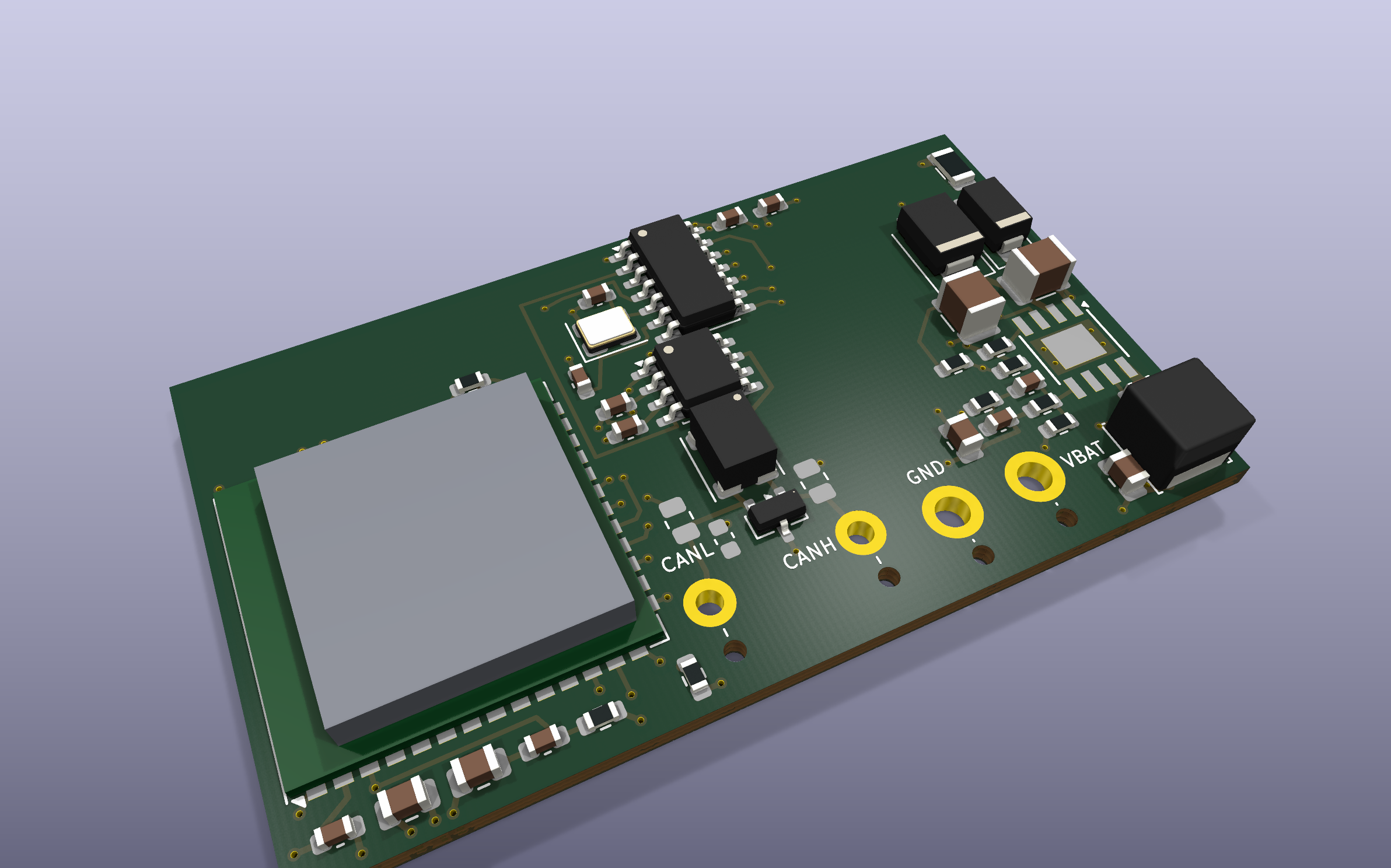
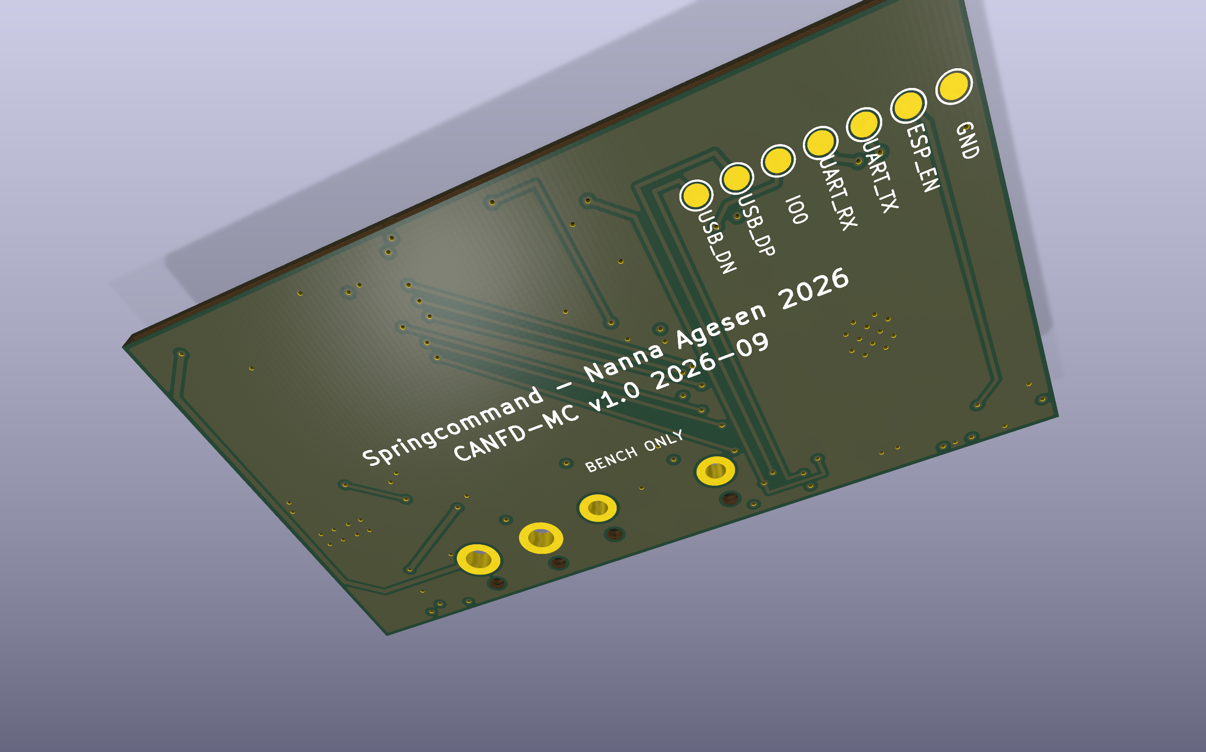
What it drops from the LilyGO board, on purpose: the isolated transceiver (one machine, one ground — the isolation was bridged the moment it was wired in, and its DC-DC was three quarters of the sleep current), the USB connector, the screw terminals, the second CAN channel, and the 120 Ω termination (the bike's bus is already terminated; a third resistor is a stub). What it adds: a 6–40 V input that survives load dump, four solder pads with strain-relief holes instead of connectors, and a ~10 µA regulator so the board can live on the battery.
canfd-mc.kicad_pro / .kicad_sch / .kicad_pcb   KiCad 10 project — placed, routed, DRC clean
canfd_local.pretty/                            three project footprints (solder pads with relief
                                               holes, Murata DLW43SH with Murata's pin numbering)
production/                                    what JLCPCB was sent: Gerber zip, BOM, CPL
docs/design-document.html                      the full design document: BOM, net list, the
                                               LM5164 calculation, layout rules, checklist
docs/BUILD-NOTES.md                            build, ordering and bring-up notes
docs/WIRING-PARTS.md antenna and service-connector cable to orderFour wires from the service connector, soldered to plated pads along the bottom edge — CANL · CANH · GND · VBAT. Each pad has an unplated 1.2 mm hole 3 mm inboard: thread the wire up through the hole and down into the pad, so the board takes the strain instead of the solder joint. No shield pad: the bus shield is grounded at the ECM.
Flashing pads on the back, 2.54 mm pitch — GND · EN · TX · RX · IO0 · USB_D+ · USB_D−. First flash goes over the ESP32-S3's native USB (a cut USB cable on D+/D−/GND; the board is powered from 12 V, not from USB). After that, OTA.
| Input | 6–40 V (LM5164 is rated to 100 V; the TVS clamps load dump at ~39 V) |
| UVLO | on at 7.0 V, off at 6.5 V |
| Output | 3.3 V, 300 kHz, 1 A rating (real load < 0.5 A) |
| Protection | 1 A fuse, series Schottky (reverse polarity), SMBJ24CA |
The buck was calculated from the LM5164 datasheet equations and confirmed with TI's WEBENCH: RON, inductor and bootstrap capacitor came out identical.
Rev 1.0. Ordered from JLCPCB in September 2026 (5 boards, assembled). Reviewed (docs/REVIEW-rev1.0.md): net list confirmed against the datasheets, three notes for rev 1.1. Not yet tested on hardware — this is a first revision, and the bring-up checklist in the design document is the plan for finding out what it got wrong.
Things a second revision might change are tracked in the design document's open-points table.
MIT, like the firmware. Design and silkscreen: Springcommand — Nanna Agesen 2026.
| Qty | Value | Footprint | References |
|---|---|---|---|
| 4 | 22uF 10V | Capacitor_SMD:C_0805_2012Metric | C3, C4, C12, C13 |
| 3 | 100nF | Capacitor_SMD:C_0603_1608Metric | C14, C16, C18 |
| 3 | 10k | Resistor_SMD:R_0603_1608Metric | R7, R8, R9 |
| 2 | 100k | Resistor_SMD:R_0603_1608Metric | R2, R6 |
| 2 | 2.2nF 50V | Capacitor_SMD:C_0603_1608Metric | C5, C6 |
| 2 | 22pF C0G | Capacitor_SMD:C_0603_1608Metric | C10, C11 |
| 2 | 4.7uF 100V X7R | Capacitor_SMD:C_1210_3225Metric | C1, C2 |
| 2 | 60.4R | Resistor_SMD:R_0805_2012Metric | RT1, RT2 |
| 1 | 10uF | Capacitor_SMD:C_0603_1608Metric | C15 |
| 1 | 150k | Resistor_SMD:R_0603_1608Metric | R4 |
| 1 | 1A 63V | Fuse:Fuse_1206_3216Metric | F1 |
| 1 | 1uF | Capacitor_SMD:C_0603_1608Metric | C19 |
| 1 | 22uH | Inductor_SMD:L_Changjiang_FNR5040S | L2 |
| 1 | 27.4k | Resistor_SMD:R_0603_1608Metric | R1 |
| 1 | 270pF C0G | Capacitor_SMD:C_0603_1608Metric | C7 |
| 1 | 365k | Resistor_SMD:R_0603_1608Metric | R5 |
| 1 | 4.7nF | Capacitor_SMD:C_0603_1608Metric | CT1 |
| 1 | 4.7uF | Capacitor_SMD:C_0603_1608Metric | C17 |
| 1 | 40MHz 15pF | Crystal:Crystal_SMD_3225-4Pin_3.2x2.5mm | X1 |
| 1 | 57.6k | Resistor_SMD:R_0603_1608Metric | R3 |
| 1 | CANH | canfd_local:SolderPad_D1.5mm_Relief | P3 |
| 1 | CANL | canfd_local:SolderPad_D1.5mm_Relief | P4 |
| 1 | DLW43SH101XK2L | canfd_local:L_CommonModeChoke_Murata_DLW43SH | L1 |
| 1 | ESP32-S3-WROOM-1U-N16R8 | RF_Module:ESP32-S3-WROOM-1U | U1 |
| 1 | ESP_EN | TestPoint:TestPoint_Pad_D1.5mm | TP5 |
| 1 | GND | canfd_local:SolderPad_D2.0mm_Relief | P2 |
| 1 | GND | TestPoint:TestPoint_Pad_D1.5mm | TP1 |
| 1 | IO0 | TestPoint:TestPoint_Pad_D1.5mm | TP4 |
| 1 | LM5164DDAR | Package_SO:TI_SO-PowerPAD-8_ThermalVias | U3 |
| 1 | MCP2518FDT-E/SL | Package_SO:SOIC-14_3.9x8.7mm_P1.27mm | U2 |
| 1 | PESD2CAN | Package_TO_SOT_SMD:SOT-23 | D3 |
| 1 | SMBJ24CA | Diode_SMD:D_SMB | D2 |
| 1 | SS36 | Diode_SMD:D_SMA | D1 |
| 1 | TCAN332GDR | Package_SO:SOIC-8_3.9x4.9mm_P1.27mm | U4 |
| 1 | UART_RX | TestPoint:TestPoint_Pad_D1.5mm | TP7 |
| 1 | UART_TX | TestPoint:TestPoint_Pad_D1.5mm | TP6 |
| 1 | USB_DN | TestPoint:TestPoint_Pad_D1.5mm | TP2 |
| 1 | USB_DP | TestPoint:TestPoint_Pad_D1.5mm | TP3 |
| 1 | VBAT | canfd_local:SolderPad_D2.0mm_Relief | P1 |
darshp848/bldc-controller-60v
60 V, 20 A / 80 A peak BLDC motor controller that fits the MD80 v3.0 mounting. KiCad 10, 6 layers.


dragonlock2/kicadboards
Offsite backup for the miscellaneous KiCad boards that don't fit elsewhere

Maritime-Hacking-Village/Badge-2025
Public repository for the official MHV 2025 badge.

jonahsaunders/planar-studio
KiCad extension for the copper you can't buy as a part — design planar inductors, transformers, PCB motor stators, filters, and antennas, with electrical modeling and direct write-back to your board.


It measures 55 × 32 mm and has 4 copper layers, 1.6 mm thick.
51 parts, built around the ESP32-S3-WROOM-1U-N16R8, LM5164DDAR, MCP2518FDT-E/SL-HX and DLW43SH101XK2L. The full list of its parts is on this page, with links to each part's symbol and footprint where PCBKit's library has them.
From the Prinsessen/canfd-mc-hardware repository on GitHub, at the commit this page was made from: the board is canfd-mc.kicad_pcb and its schematic canfd-mc.kicad_sch. PCBKit opens the board in the browser, with nothing to install.
Its repository publishes it under the MIT licence: you may reuse it on that licence's terms (keep the author's notice, and for a copyleft licence share your changes alike).