PlugInDC Load
janni0609/DC-Load
A programmable DC electronic load built on the Raspberry Pi Pico 2 (RP2350). It sinks a user-defined current from a DC source under test and measures voltage, current, power, capacity, and energy in real time on a…

A device to assist in extending the life of EBike batteries.
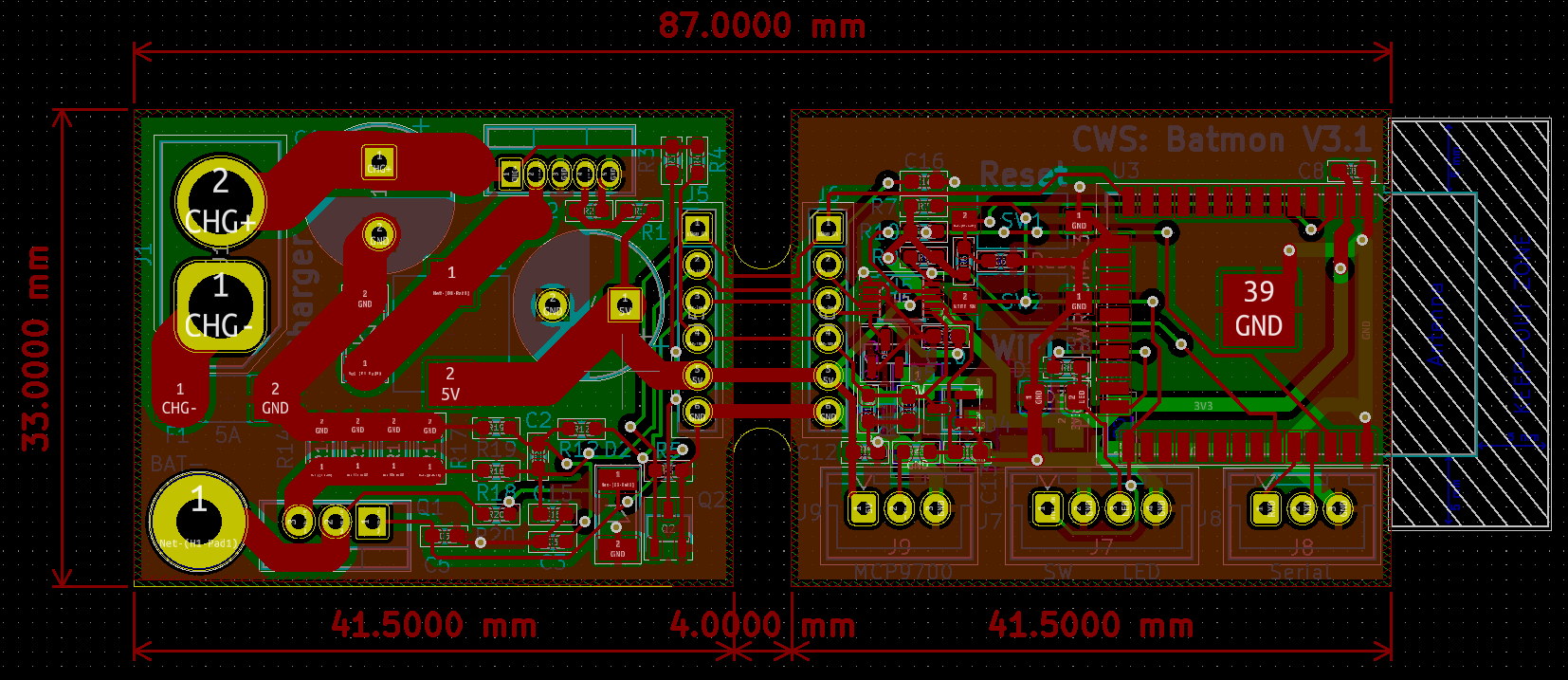
Batmon is an open-source printed circuit board by pjaos, from the pjaos/batmon repository on GitHub, published under the MIT licence. It is a 2-layer board of 87 × 33 mm with 58 parts on 52 nets, routed with 399 tracks and 40 vias.
It is built around the ESP32-WROOM-32, ADS1115IDGS and LM2576HVS-ADJ, with the MCP9700-E/TT, LM1117-3.3 and IRF520NPBF among its other parts. Its parts include 20 resistors, 16 capacitors, 6 connectors, 5 diodes and 4 ICs. It belongs with the ESP32 boards of this library.
The batmon device connects to a Lithium ION battery (primarily aimed at Ebike batteries) and allows the user to trade off the lifetime of the battery against the maximum single charge. The life of a lithium ION cell is affected by many things, the maximum charge level of the cell, the temperature of the cell, the maximum discharge of the cell etc. The batmon device allows the user to limit the maximum charge voltage of the cell to reduce stresses on the battery chemistry.
For example if the maximum charge voltage of a Lithium ION cell is set to 4.1 volts per cell rather than the maximum of 4.2 volts per cell then the number of charge/discharge cycles that the battery is capable of could be doubled. The trade off for this is that you will loose about 10 % of the range on a single charge. If set to 4.0 volts per cell then the number of charge/discharge cycles that the battery is capable of could be increased by four times. The trade off for this is that you will loose about 25 % of the range on a single charge. The batmon device allows the user to set this trade off by selecting the maximum charge voltage in five 0.05 volt steps from 4.2 to 4.0 volts.
The device also ensures that the battery is not charged when to cold or hot which also limits the batteries lifetime. Charging at temperatures of 0°C or below can also be dangerous.
As stated previously this project is primarily aimed at improving the lifetime of Ebike batteries although the hardware could be used for other battery voltages with slight changes to the software. The device provides a WiFi connection. This can connect to your home WiFi network or run in stand alone (AP) mode. The Yview App can be used (Android phone/tablet or a Windows, Linux PC) to access the state of the battery (charge voltage/current etc) and configure the device settings.
An initial set of requirements for the system is shown below.
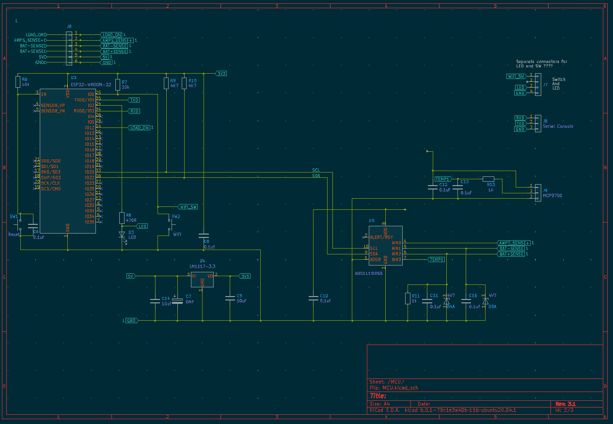
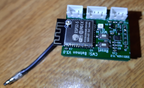
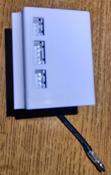
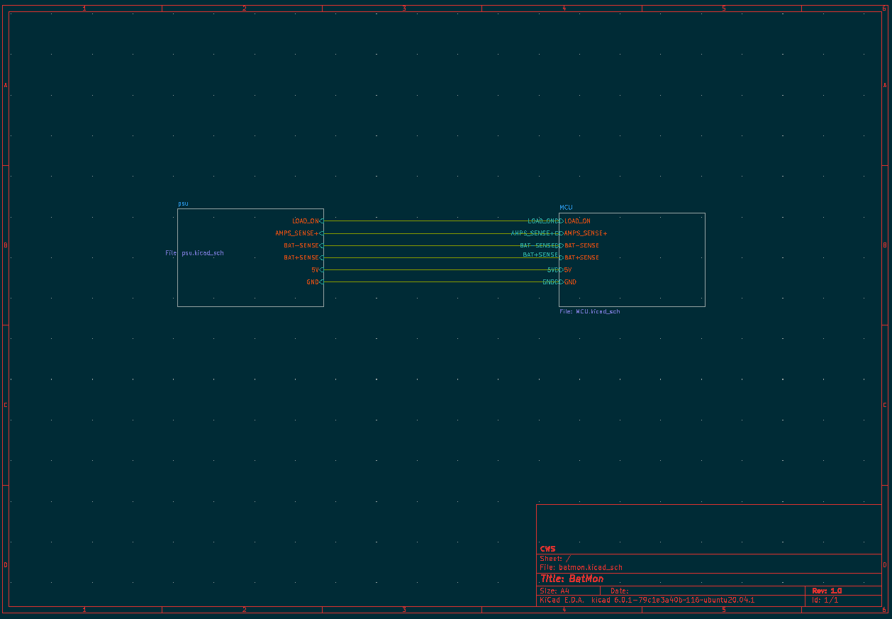
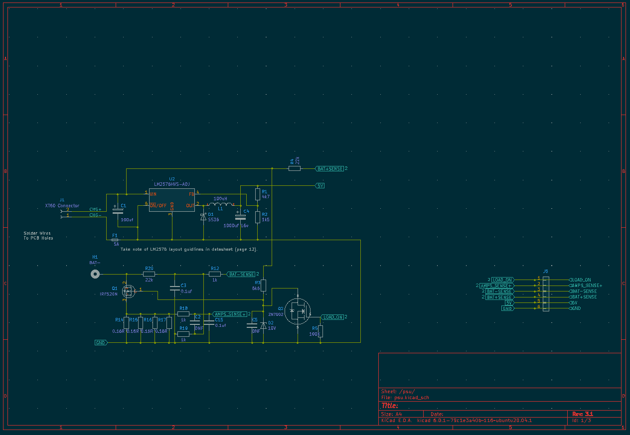
The hardware design uses an ESP32 CPU which provides the WiFi connectivity. An ADS1115 I2C 16 bit ADC device is used to measure the battery voltage, charge current and battery temperature. A Mosfet is used to turn off the battery charge once it reaches the configured charge voltage. The case for the module was 3D printed to provide a robust mount for the module inside the battery case.
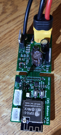
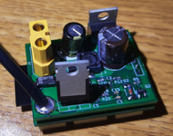
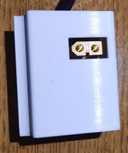
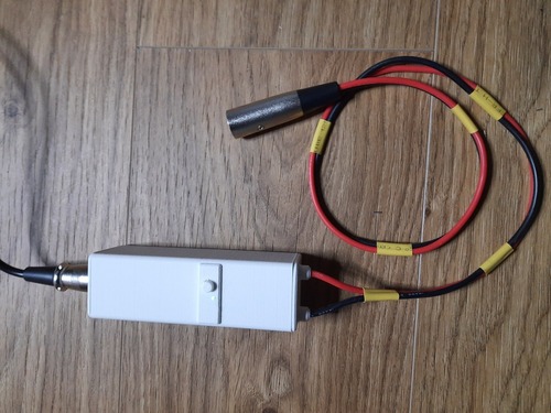
Module installed into case in charger lead.
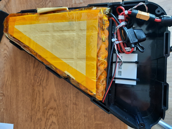
Module installed inside Ebike battery box.
The software that runs on the device is written in C and uses the Mongoose OS.
It provides a web interface and integrates with the YView Iot archetecture.
The web interface is shown below.
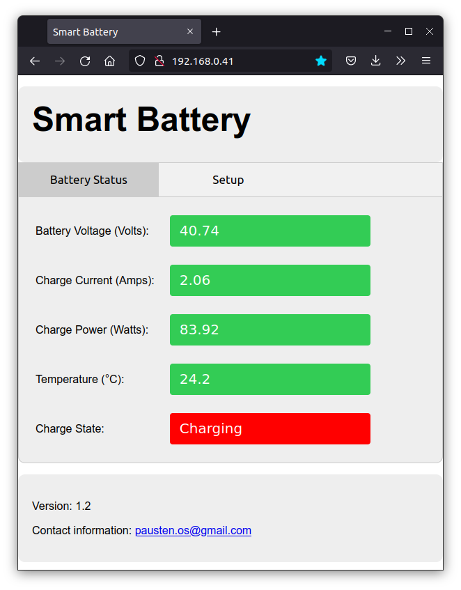
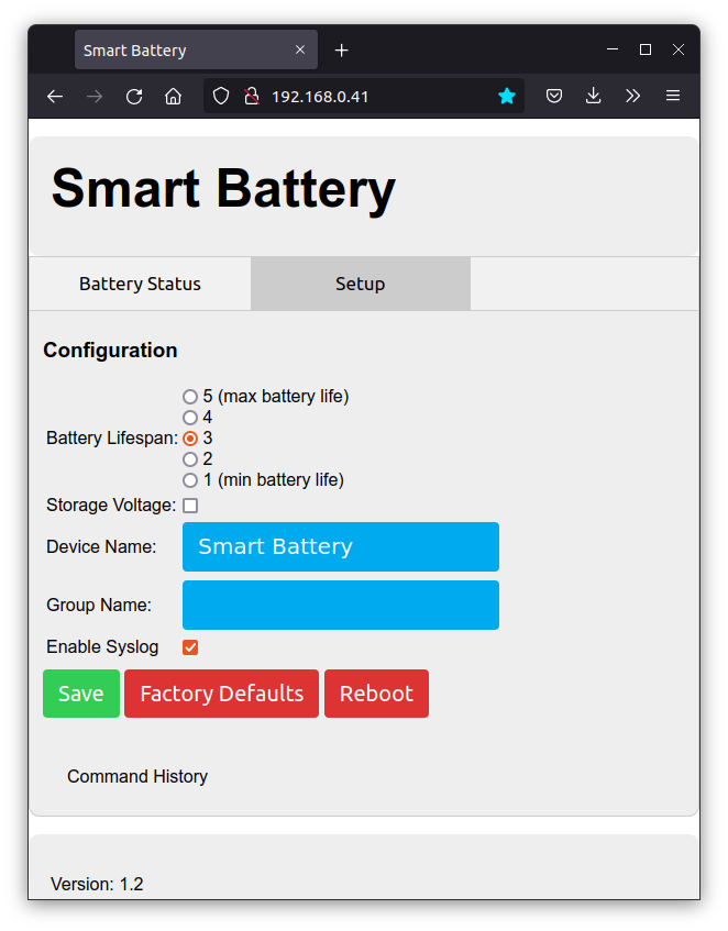
The configuration page allow the user to trade off battery charge level against the longevity of the battery pack via the 5 radio buttons at the top of the page.
The default is 3 with charges the battery pack to 4.1 volts per cell. This setting should approximately double the life (number of charge discharge cycles) when compared option 1. EBike battery chargers will normally charge a battery pack to this level. If option 5 is selected then the life of the battery should be approximately 4 times longer when compared to option 1.
The storage voltage checkbox can be selected if the user wishes to store the ebike for some time (E.G through the winter) and maximise the battery performance. This charges the battery to 3.7 volts.
The Device name can be set which sets the name that the device will appear as in the YView Iot network.
The group name can be set if the user wishes to partition the Iot network such that some users can see some devices.
The Enable syslog option is used for debugging and sends debugging information via the syslog protocol to the server running the YView Iot gateway process.
The save button will apply the configuration selected. The other buttons names are self explanatory.
| Qty | Value | Footprint | References |
|---|---|---|---|
| 9 | 0.1uf | Capacitor_SMD:C_0603_1608Metric_Pad1.08x0.95mm_HandSolder | C3, C6, C8, C10, C11, C12, C13, C15, C16 |
| 4 | 0.16R | Resistor_SMD:R_1206_3216Metric_Pad1.30x1.75mm_HandSolder | R14, R15, R16, R17 |
| 4 | 1k | Resistor_SMD:R_0603_1608Metric_Pad0.98x0.95mm_HandSolder | R11, R12, R18, R19 |
| 2 | 10k | Resistor_SMD:R_0603_1608Metric_Pad0.98x0.95mm_HandSolder | R6, R7 |
| 2 | 10uf | Capacitor_SMD:C_1206_3216Metric_Pad1.33x1.80mm_HandSolder | C9, C14 |
| 2 | 22k | Resistor_SMD:R_0603_1608Metric_Pad0.98x0.95mm_HandSolder | R4, R20 |
| 2 | 4K7 | Resistor_SMD:R_0603_1608Metric_Pad0.98x0.95mm_HandSolder | R9, R10 |
| 2 | 4V7 | Package_TO_SOT_SMD:SOT-23 | D4, D5 |
| 2 | Conn_01x06 | Connector_PinHeader_2.54mm:PinHeader_1x06_P2.54mm_Vertical | J5, J6 |
| 2 | DNF | Capacitor_SMD:C_0603_1608Metric_Pad1.08x0.95mm_HandSolder | C2, C5 |
| 1 | 1000uf 16v | Capacitor_THT:CP_Radial_D10.0mm_P5.00mm | C4 |
| 1 | 100K | Resistor_SMD:R_0603_1608Metric_Pad0.98x0.95mm_HandSolder | R5 |
| 1 | 100uH | PJA_Inductors:Sumida_CDRH74 | L1 |
| 1 | 100uf | Capacitor_THT:CP_Radial_D10.0mm_P5.00mm | C1 |
| 1 | 10V | Diode_SMD:D_MELF | D2 |
| 1 | 1K | Resistor_SMD:R_0603_1608Metric_Pad0.98x0.95mm_HandSolder | R13 |
| 1 | 1k5 | Resistor_SMD:R_0603_1608Metric_Pad0.98x0.95mm_HandSolder | R2 |
| 1 | 2N7002 | Package_TO_SOT_SMD:TSOT-23 | Q2 |
| 1 | 470R | Resistor_SMD:R_0603_1608Metric_Pad0.98x0.95mm_HandSolder | R8 |
| 1 | 4k7 | Resistor_SMD:R_0603_1608Metric_Pad0.98x0.95mm_HandSolder | R1 |
| 1 | 5A | PJA_Fuses:Scherter_OMT125 | F1 |
| 1 | 5k6 | Resistor_SMD:R_0603_1608Metric_Pad0.98x0.95mm_HandSolder | R3 |
| 1 | ADS1115IDGS | Package_SO:TSSOP-10_3x3mm_P0.5mm | U5 |
| 1 | BAT- | MountingHole:MountingHole_3.2mm_M3_Pad | H1 |
| 1 | DNF | Capacitor_Tantalum_SMD:CP_EIA-6032-20_AVX-F_Pad2.25x2.35mm_HandSolder | C7 |
| 1 | ESP32-WROOM-32 | RF_Module:ESP32-WROOM-32 | U3 |
| 1 | IRF520N | Package_TO_SOT_THT:TO-220-3_Vertical | Q1 |
| 1 | LED | Diode_SMD:D_1206_3216Metric_Pad1.42x1.75mm_HandSolder | D3 |
| 1 | LM1117-3.3 | Package_TO_SOT_SMD:SOT-223-3_TabPin2 | U4 |
| 1 | LM2576HVS-ADJ | Package_TO_SOT_THT:TO-220-5_Vertical | U2 |
| 1 | MCP9700 | Connector_JST:JST_XH_B3B-XH-A_1x03_P2.50mm_Vertical | J9 |
| 1 | Reset | PJA_Switches:switch_SPST_5mmx3mmx2.5mm | SW1 |
| 1 | SS36 | Diode_SMD:D_MELF | D1 |
| 1 | SW_&_LED | Connector_JST:JST_XH_B4B-XH-A_1x04_P2.50mm_Vertical | J7 |
| 1 | Serial Console | Connector_JST:JST_XH_B3B-XH-A_1x03_P2.50mm_Vertical | J8 |
| 1 | WiFi | PJA_Switches:switch_SPST_5mmx3mmx2.5mm | SW2 |
| 1 | XT60 Connector | Connector_AMASS:AMASS_XT60-F_1x02_P7.20mm_Vertical | J1 |
It measures 87 × 33 mm and has 2 copper layers, 1.6 mm thick.
58 parts, built around the ESP32-WROOM-32, ADS1115IDGS, LM2576HVS-ADJ and MCP9700-E/TT. The full list of its parts is on this page, with links to each part's symbol and footprint where PCBKit's library has them.
From the pjaos/batmon repository on GitHub, at the commit this page was made from: the board is hardware/schemtic_pcb/batmon.kicad_pcb and its schematic hardware/schemtic_pcb/MCU.kicad_sch. PCBKit opens the board in the browser, with nothing to install.
Its repository publishes it under the MIT licence: you may reuse it on that licence's terms (keep the author's notice, and for a copyleft licence share your changes alike).

janni0609/DC-Load
A programmable DC electronic load built on the Raspberry Pi Pico 2 (RP2350). It sinks a user-defined current from a DC source under test and measures voltage, current, power, capacity, and energy in real time on a…

pjaos/temper
The hardware and software to monitor temperature and humidity via 4 sensors.

ChengminLi/AI-PCB-layout
AI agent skill for designing and reviewing power-electronics PCBs, with a human review gate after every step


mwalsh161/pirled
Design goals: 1. A single ESP8266 governs up to 4 LEDs + 4 PIR sensors (+4 virtual signals). 2. Any LED can trigger on/off with any grouping of PIR sensors/virtual signals. - Note, logical OR with each other hard-coded.

spiwocoal/547452
Convertidor DC/DC topología SEPIC para ramo Taller de sistemas electrónicos