
2 layers65 × 56 mm

 pief/PiStripe_uHAT5
LED stripe add-on board for the Raspberry Pi
PiStripe uHAT is an open-source printed circuit board by pief, from the pief/PiStripe_uHAT repository on GitHub. It is a 2-layer board of 65 × 30 mm with 46 parts on 27 nets, routed with 316 tracks and 35 vias.
It is built around the TPS54202DDC, CAT24C32WI-GT3 and DMMT5401, with the DMG2305UX-13 and SRU1048-150Y among its other parts. Its parts include 16 resistors, 9 capacitors, 4 transistors, 4 connectors and 3 ICs.


The current v0.7 revision of the PiStripe uHAT has been successfully built and tested with the following remarks nonwithstanding:
The PiStripe uHAT uses the following GPIO pins:
| GPIO pins | Pin name | Usage | Exclusive |
|---|---|---|---|
| 1, 17 | +3.3V | IR receiver, ID EEPROM | No |
| 2, 4 | +5V | Back powering Raspberry Pi | No |
| 6, 9, 14, 20, 25, 30, 34, 39 | GND | Ground | No |
| 19 | GPIO10_SPI_MOSI | LED color 1 (e.g. Red) | Yes |
| 21 | GPIO09_SPI_MISO | LED color 2 (e.g. Green) | Yes |
| 22 | GPIO25 | IR receiver data | Yes |
| 23 | GPIO11_SPI_CLK | LED color 3 (e.g. Blue) | Yes |
| 27 | ID_SD | ID EEPROM I2C Data | No |
| 28 | ID_SC | ID EEPROM I2C Clock | No |
There are two jumpers:
| Jumper | Name | Function |
|---|---|---|
| JP1 | GPIO_PWR | Open: Raspberry Pi is powered over Micro USB connector |
| GPIO_PWR | Closed: Enable back powering the Raspberry Pi via GPIO | |
| JP2 | WR_EN | Open: Normal usage |
| WR_EN | Closed: ID EEPROM can be programmed |
Whether you leave JP1 open or closed depends on whether you want to use the "back powering" feature, thus requiring only the LED stripe's +12V power supply, or keep supplying the Raspberry Pi via its Micro USB connector. Even if you accidentally close JP1 and still connect power to the Pi's Micro USB connector, nothing should go wrong thanks to the "perfect" reverse current blocking diode.
JP2 should only be closed once to program the ID EEPROM (no instructions and software for this yet) and stay open afterwards to prevent accidental flashing.
The board's schematic and PCB have been designed with KiCad, a really powerful Open Source EDA solution and a worthy alternative to commercial products such as Eagle.
Here's an image of the schematic:
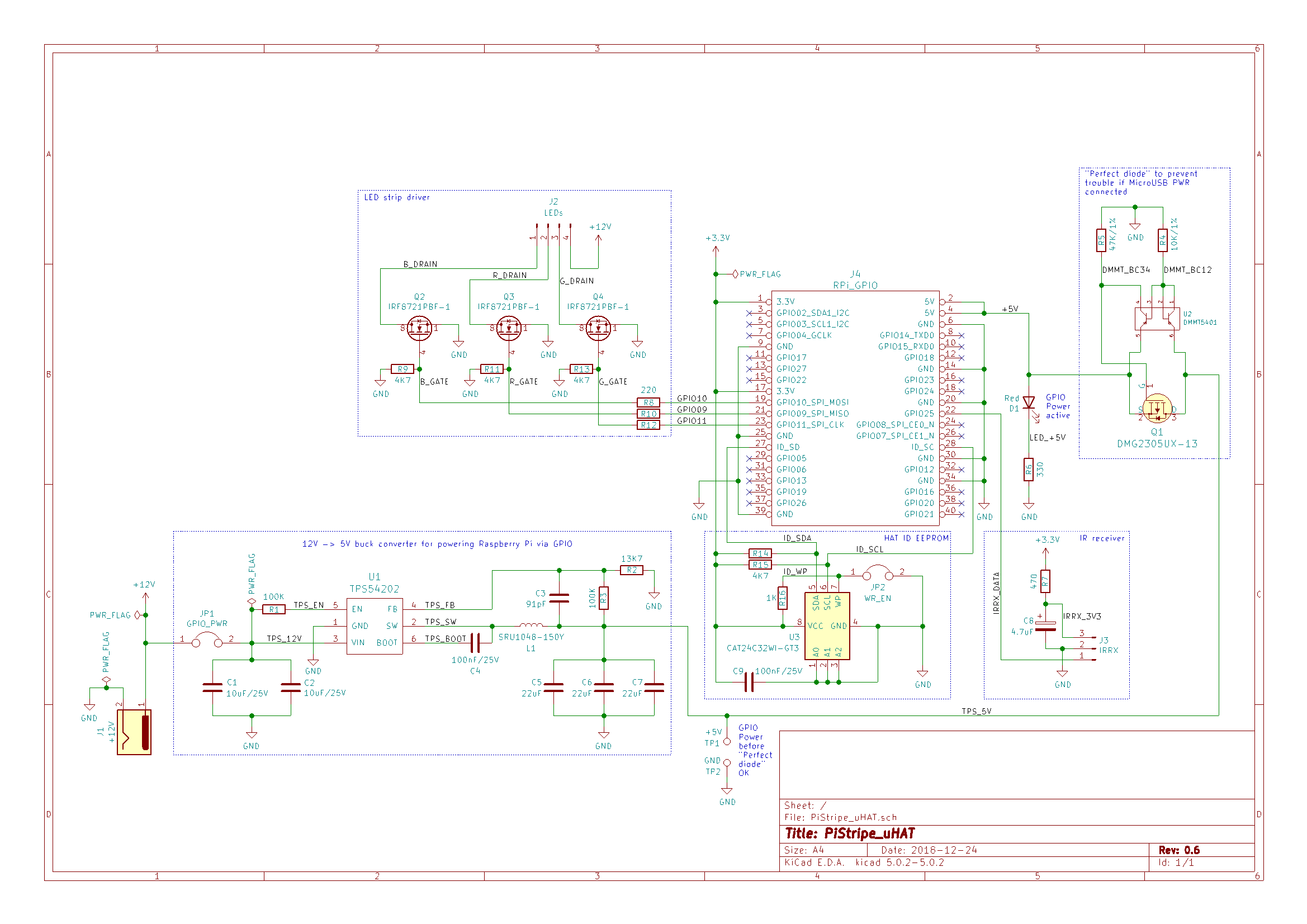
As you can see, the schematic is clearly divided into different blocks that corrospond to the functions listed above, so comparisons with the original sources for the schematics (see Credits) should be rather easy.
Here are some images of the PCB:
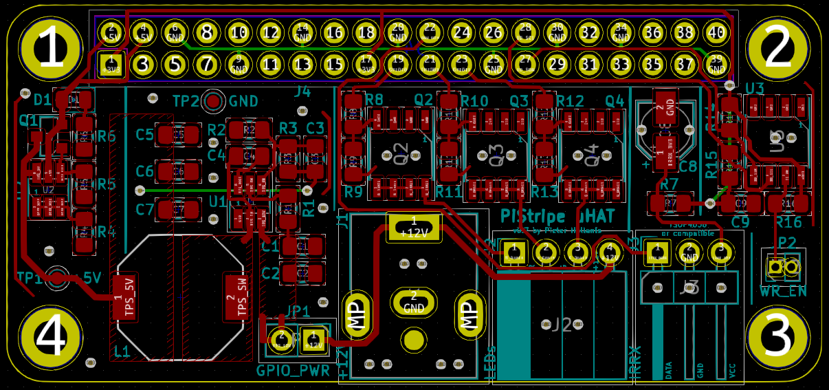
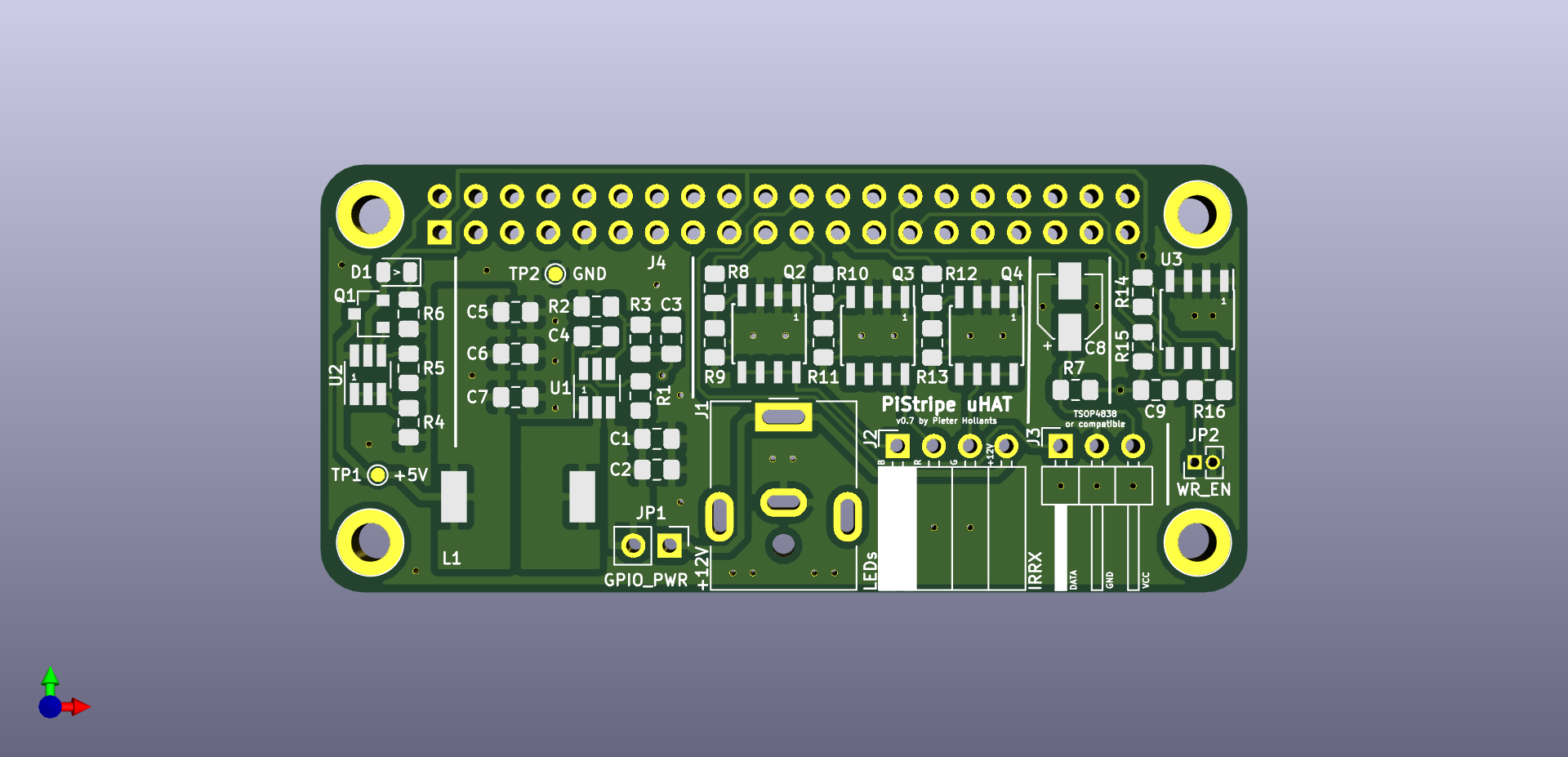
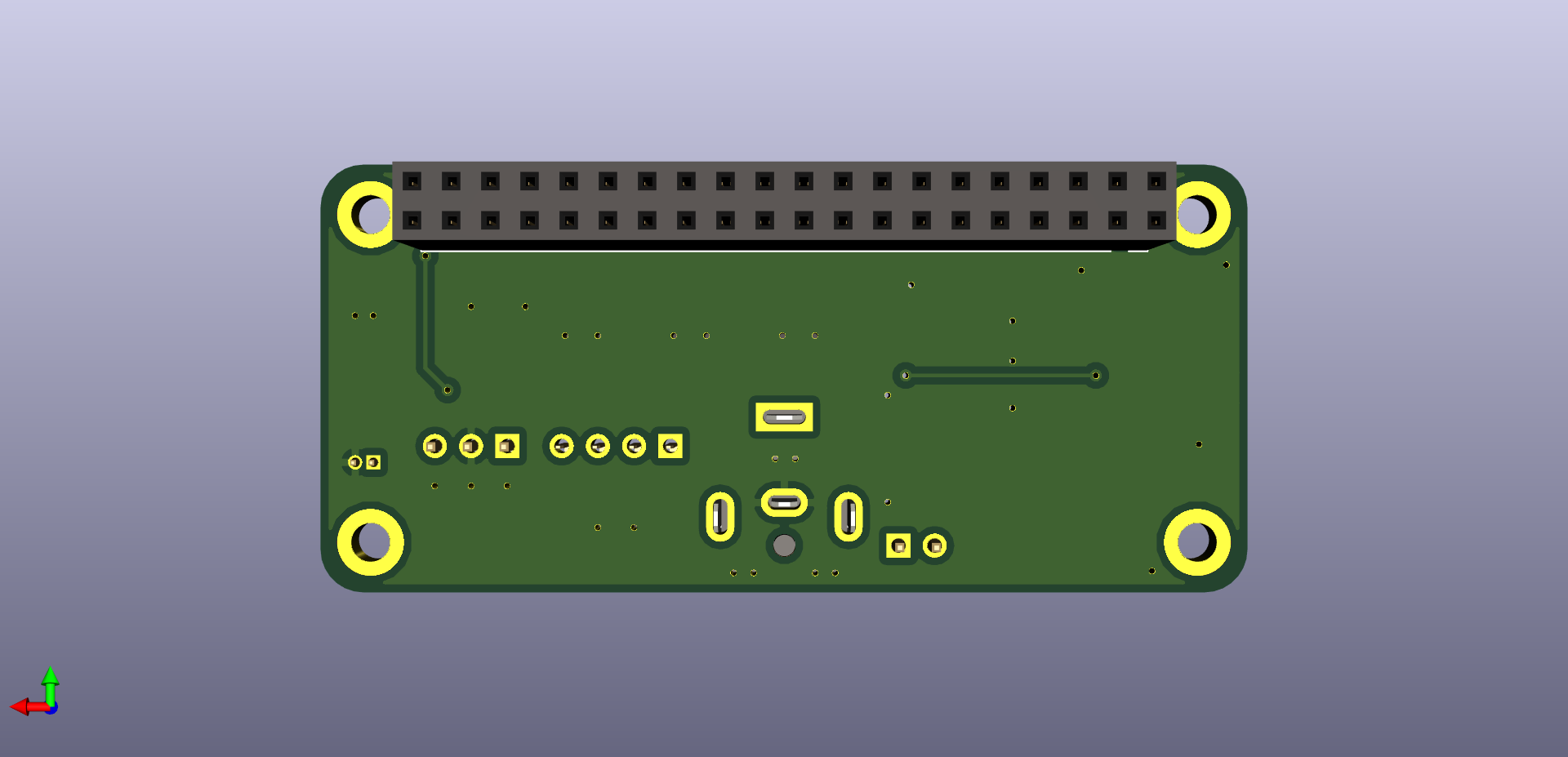
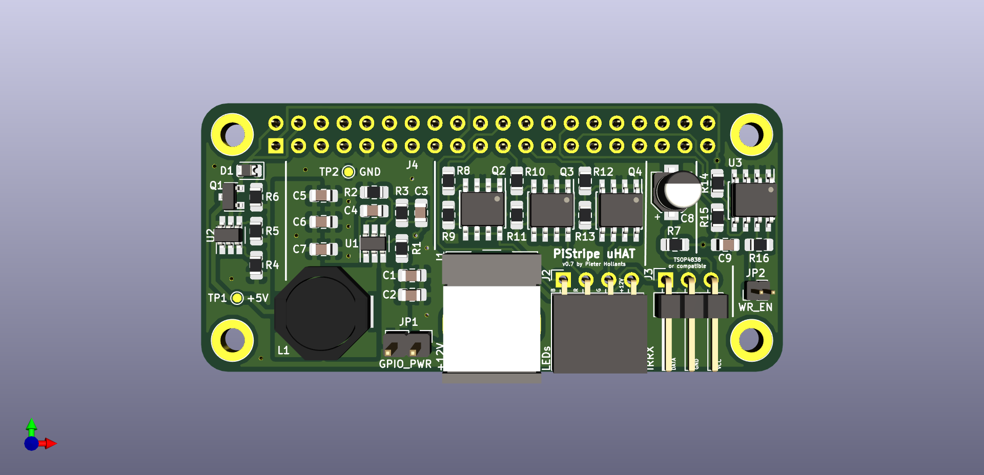
Like the schematic, the PCB has guiding lines printed on top to isolate the different function blocks.
Please consult the CSV part list for details.
I'm not really inventing something new here but merely combining existing stuff into something new, so I'm standing on the shoulders of giants and try to give appropriate credits here. A big "Thank you" to the following people:
Connector-ML.lib for the schematic. The template is licensed under the MIT license.dk_Transistors-FETs-MOSFETs-Single.lib for the schematic. The library is licensed under the CC-BY-SA 4.0 license.tps54202.lib for the schematic.DMMT5401.lib for the schematic. They are licensed under the CERN Open Hardware License v1.1.SRU1048.kicad_mod in the PCB design. Since it didn't provide a 3D model, I modified it to use the one from the following paragraph. Philipp did not explicitly specify a license, so I'll assume CC-BY-SA.SRU1048.wrl together with the footprint in the previous paragraph. They use their own license.The PiStripe uHAT PCB and its design files are licensed CC-BY-SA.
| Qty | Value | Footprint | References |
|---|---|---|---|
| 5 | 4K7 | Resistor_SMD:R_0805_2012Metric_Pad1.15x1.40mm_HandSolder | R9, R11, R13, R14, R15 |
| 4 | MountingHole_2.7mm_M2.5_DIN965_Pad | Mounting_Holes:MountingHole_2.7mm_M2.5_DIN965_Pad | REF1, REF2, REF3, REF4 |
| 3 | 220 | Resistor_SMD:R_0805_2012Metric_Pad1.15x1.40mm_HandSolder | R8, R10, R12 |
| 3 | 22uF | Capacitor_SMD:C_0805_2012Metric_Pad1.15x1.40mm_HandSolder | C5, C6, C7 |
| 3 | IRF8721PBF-1 | Package_SO:SOIC-8_3.9x4.9mm_P1.27mm | Q2, Q3, Q4 |
| 2 | 100K | Resistor_SMD:R_0805_2012Metric_Pad1.15x1.40mm_HandSolder | R1, R3 |
| 2 | 100nF/25V | Capacitor_SMD:C_0805_2012Metric_Pad1.15x1.40mm_HandSolder | C4, C9 |
| 2 | 10uF/25V | Capacitor_SMD:C_0805_2012Metric_Pad1.15x1.40mm_HandSolder | C1, C2 |
| 1 | +12V | Connector_BarrelJack:BarrelJack_CUI_PJ-063AH_Horizontal | J1 |
| 1 | +5V | TestPoint:TestPoint_Pad_D1.0mm | TP1 |
| 1 | 10K/1% | Resistor_SMD:R_0805_2012Metric_Pad1.15x1.40mm_HandSolder | R4 |
| 1 | 13K7 | Resistor_SMD:R_0805_2012Metric_Pad1.15x1.40mm_HandSolder | R2 |
| 1 | 1K | Resistor_SMD:R_0805_2012Metric_Pad1.15x1.40mm_HandSolder | R16 |
| 1 | 330 | Resistor_SMD:R_0805_2012Metric_Pad1.15x1.40mm_HandSolder | R6 |
| 1 | 4.7uF | Capacitor_SMD:CP_Elec_4x5.8 | C8 |
| 1 | 470 | Resistor_SMD:R_0805_2012Metric_Pad1.15x1.40mm_HandSolder | R7 |
| 1 | 47K/1% | Resistor_SMD:R_0805_2012Metric_Pad1.15x1.40mm_HandSolder | R5 |
| 1 | 91pF | Capacitor_SMD:C_0805_2012Metric_Pad1.15x1.40mm_HandSolder | C3 |
| 1 | CAT24C32WI-GT3 | Package_SO:SOIC-8_3.9x4.9mm_P1.27mm | U3 |
| 1 | DMG2305UX-13 | Package_TO_SOT_SMD:SOT-23 | Q1 |
| 1 | DMMT5401 | Package_TO_SOT_SMD:SOT-23-6_Handsoldering | U2 |
| 1 | GND | TestPoint:TestPoint_Pad_D1.0mm | TP2 |
| 1 | GPIO_PWR | Connector_PinHeader_2.54mm:PinHeader_1x02_P2.54mm_Vertical | JP1 |
| 1 | IRRX | pief:PinHeader_1x03_P2.54mm_Horizontal_Mirrored | J3 |
| 1 | LEDs | Connector_PinSocket_2.54mm:PinSocket_1x04_P2.54mm_Horizontal | J2 |
| 1 | RPi_GPIO | Connector_PinSocket_2.54mm:PinSocket_2x20_P2.54mm_Vertical | J4 |
| 1 | Red | Diode_SMD:D_0805_2012Metric | D1 |
| 1 | SRU1048-150Y | Virtex7:SRU1048 | L1 |
| 1 | TPS54202 | Package_TO_SOT_SMD:SOT-23-6_Handsoldering | U1 |
| 1 | WR_EN | Connector_PinHeader_1.27mm:PinHeader_1x02_P1.27mm_Vertical | JP2 |


jntaimo/2.12-PCB
This is the PCB design for the MIT Intro to Robotics class 2.12

Wren6991/Snowflake-FPGA
A cheap iCE40 development board, designed on and for Raspberry Pi

AnaviTechnology/anavi-infrared
ANAVI Infrared pHAT is an open source hardware Raspberry Pi pHAT (add-on board) for rapid prototyping of Internet of Things (IoT) powered by free and open source software. It features:

AnaviTechnology/anavi-gardening
ANAVI Gardening uHAT is an open source hardware add-on board for Raspberry Pi that helps you develop smart solutions for monitoring and growing plants.
It measures 65 × 30 mm and has 2 copper layers, 1.6 mm thick.
46 parts, built around the TPS54202DDC, CAT24C32WI-GT3, DMMT5401 and DMG2305UX-13. The full list of its parts is on this page, with links to each part's symbol and footprint where PCBKit's library has them.
From the pief/PiStripe_uHAT repository on GitHub, at the commit this page was made from: the board is Hardware/PiStripe_uHAT.kicad_pcb. PCBKit opens the board in the browser, with nothing to install.
Its repository states no licence, so its author keeps all rights: ask pief before reusing the design.