
4 layers166.7 × 58.4 mm

The Raspberry Pi Hat
KCH is an open-source printed circuit board by srobo, from the srobo/kch-hw repository on GitHub. It is a 2-layer board of 65 × 56 mm with 153 parts on 123 nets, routed with 873 tracks and 143 vias.
It is built around the CAT24C32WI-GT3, 2N7002KDW and FM-B2020RGBA-HG, with the NCE3401AY, AO3407A and BZT52C6V8 among its other parts. Its parts include 85 resistors, 20 diodes, 16 transistors, 12 capacitors and 4 connectors.


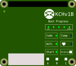
A Raspberry Pi 4 add-on board to protect and power the Pi from the v4 SR kit, and provide a visual indicator of the state of the brain board's software as detailed in the specification.
The UI is illustrated below.
The board was designed to be manufactured using JLCPCB for both the PCB and assembly. This is using as 2 layer board with single sided assembly. The two through-hole connectors are rear-mounted and manually added after.
The BOM and assembly files can be generated with KiCAD JLCPCB tools and the JLCPCB part codes are already assigned.
| Header Pin | GPIO | Function |
|---|---|---|
| 1 | - | - |
| 2 | - | 5V |
| 3 | - | - |
| 4 | - | 5V |
| 5 | - | - |
| 6 | - | GND |
| 7 | 4 | USER C Red LED |
| 8 | 14 | UART TX |
| 9 | - | GND |
| 10 | 15 | UART RX |
| 11 | 17 | USER C Blue LED |
| 12 | 18 | USER C Green LED |
| 13 | 27 | USER B Red LED |
| 14 | - | GND |
| 15 | 22 | USER B Blue LED |
| 16 | 23 | USER B Green LED |
| 17 | - | 3.3V |
| 18 | 24 | USER A Red LED |
| 19 | 10 | USER A Green LED |
| 20 | - | GND |
| 21 | 9 | Start LED |
| 22 | 25 | USER A Blue LED |
| 23 | 11 | Code LED |
| 24 | 8 | WiFi LED |
| 25 | - | GND |
| 26 | 7 | BOOT 20% LED |
| 27 | 0 | EEPROM SDA |
| 28 | 1 | EEPROM SCL |
| 29 | 5 | BOOT 40% LED |
| 30 | - | GND |
| 31 | 6 | BOOT 80% LED |
| 32 | 12 | BOOT 60% LED |
| 33 | 13 | BOOT 100% LED |
| 34 | - | GND |
| 35 | 19 | Heartbeat LED |
| 36 | 16 | Comp LED |
| 37 | 26 | Status Red LED |
| 38 | 20 | Status Green LED |
| 39 | - | GND |
| 40 | 21 | Status Blue LED |
| Qty | Value | Footprint | References |
|---|---|---|---|
| 29 | 1k | Resistor_SMD:R_0402_1005Metric | R1, R18, R20, R25, R26, R30, R32, R34, R35, R37, R39, R42, R45, R48, R50, R53 +13 |
| 26 | 10k | Resistor_SMD:R_0402_1005Metric | R4, R5, R15, R17, R19, R23, R24, R27, R33, R36, R40, R41, R44, R47, R49, R51 +10 |
| 11 | 2N7002KDW | Package_TO_SOT_SMD:SOT-363_SC-70-6 | Q6, Q7, Q8, Q9, Q10, Q11, Q12, Q13, Q14, Q15, Q16 |
| 11 | Green | LED_SMD:LED_0603_1608Metric_Pad1.05x0.95mm_HandSolder | D3, D4, D5, D7, D8, D9, D10, D11, D14, D15, D16 |
| 10 | 3k3 | Resistor_SMD:R_0402_1005Metric | R10, R11, R21, R22, R28, R29, R31, R38, R43, R46 |
| 8 | 2k2 | Resistor_SMD:R_0402_1005Metric | R52, R54, R61, R63, R70, R72, R79, R81 |
| 5 | 100n | Capacitor_SMD:C_0402_1005Metric | C1, C2, C4, C9, C10 |
| 5 | 22u | Capacitor_SMD:C_1206_3216Metric | C3, C6, C7, C8, C11 |
| 4 | 3mm_Mounting_Hole | MountingHole:MountingHole_3.2mm_M3_ISO14580_Pad | H1, H2, H3, H4 |
| 4 | FM-B2020RGBA-HG | project_footprints:FM-B2020RGBA-HG | D17, D18, D19, D20 |
| 4 | TestPoint | TestPoint:TestPoint_Pad_D2.0mm | TP1, TP2, TP3, TP4 |
| 2 | 0R | Resistor_SMD:R_0402_1005Metric | R83, R85 |
| 2 | 3k9 | Resistor_SMD:R_0402_1005Metric | R2, R3 |
| 2 | Blue | LED_SMD:LED_0603_1608Metric_Pad1.05x0.95mm_HandSolder | D12, D13 |
| 2 | DNP | Capacitor_SMD:C_0402_1005Metric | C5, C12 |
| 2 | NCE3401AY | Package_TO_SOT_SMD:SOT-23 | Q3, Q4 |
| 1 | 100k | Resistor_SMD:R_0402_1005Metric | R8 |
| 1 | 18k | Resistor_SMD:R_0402_1005Metric | R9 |
| 1 | 1k5 | Resistor_SMD:R_0402_1005Metric | R6 |
| 1 | 220R | Resistor_SMD:R_0402_1005Metric | R14 |
| 1 | 2A | Resistor_SMD:R_0603_1608Metric | F1 |
| 1 | 40HAT | Connector_PinSocket_2.54mm:PinSocket_2x20_P2.54mm_Vertical | J3 |
| 1 | 47K | Resistor_SMD:R_0402_1005Metric | R16 |
| 1 | 56k | Resistor_SMD:R_0402_1005Metric | R12 |
| 1 | 8k2 | Resistor_SMD:R_0402_1005Metric | R13 |
| 1 | AO3407A | Package_TO_SOT_SMD:SOT-23 | Q1 |
| 1 | AP63200T | Package_TO_SOT_SMD:SOT-23-6 | U2 |
| 1 | BZT52C6V8 | Diode_SMD:D_SOD-123 | D6 |
| 1 | CAT24C32WI | Package_SO:SOIC-8_3.9x4.9mm_P1.27mm | U1 |
| 1 | CTBP9550/2 | project_footprints:CTBP9550-2 | J1 |
| 1 | DMMT5401 | Package_TO_SOT_SMD:SOT-23-6 | Q5 |
| 1 | DNP | Resistor_SMD:R_0402_1005Metric | R84 |
| 1 | LOGO | project_footprints:bee | G*** |
| 1 | LOGO | project_footprints:QRRef | G*** |
| 1 | LOGO | project_footprints:SR_LOGO | G*** |
| 1 | PMV20EN | Package_TO_SOT_SMD:SOT-23 | Q2 |
| 1 | Red | LED_SMD:LED_0805_2012Metric_Pad1.15x1.40mm_HandSolder | D2 |
| 1 | SMAJ15CA | Diode_SMD:D_SMA | D1 |
| 1 | SPM6530T-3R3M | project_footprints:MWSA0603 | L1 |
| 1 | Serial | Connector_PinHeader_2.54mm:PinHeader_1x06_P2.54mm_Vertical | J4 |
| 1 | Write EEPROM | Connector_PinHeader_2.54mm:PinHeader_1x02_P2.54mm_Vertical | J2 |
The 152 most common of 153 parts.


RT-CUSTOMZ/InfinityMirror
A small inifinity mirror using WLED on an ESP8266

mp035/grbl_controller
An esp32 GRBL Controller that can be used as a drop-in replacement for Weihong NCStudio Motion Cards


It measures 65 × 56 mm and has 2 copper layers, 1.53 mm thick.
153 parts, built around the CAT24C32WI-GT3, 2N7002KDW, FM-B2020RGBA-HG and NCE3401AY. The full list of its parts is on this page, with links to each part's symbol and footprint where PCBKit's library has them.
From the srobo/kch-hw repository on GitHub, at the commit this page was made from: the board is pcb/KCH.kicad_pcb and its schematic pcb/KCH.kicad_sch. PCBKit opens the board in the browser, with nothing to install.
Its repository states no licence, so its author keeps all rights: ask srobo before reusing the design.