
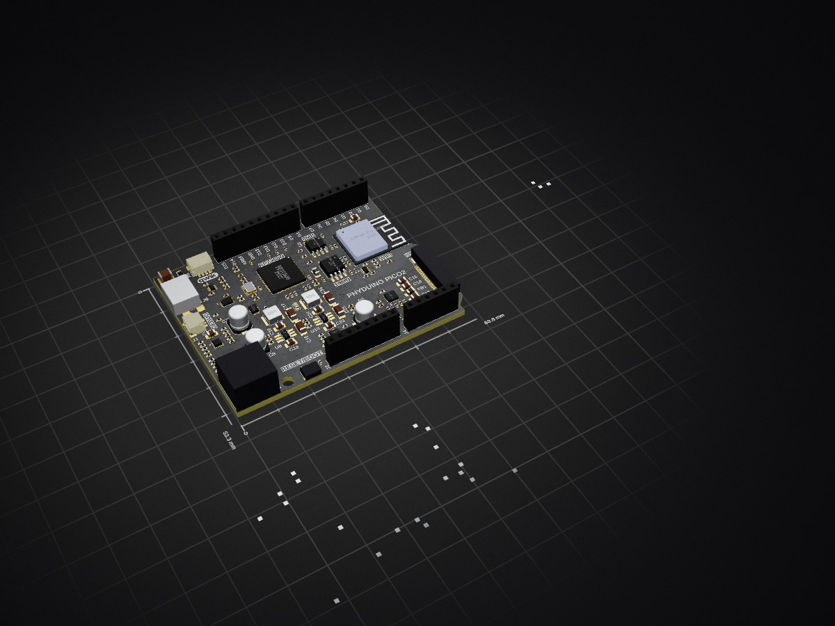
2 layers68.6 × 53.3 mm
 perc-sw/phyduino_pico2
CAD files for the student workshop Phyduino Pico2 Arduino IDE compatible board.
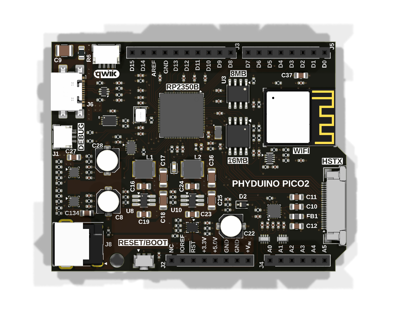
Phyduino pico2 is an open-source printed circuit board by perc-sw, from the perc-sw/phyduino_pico2 repository on GitHub, published under the GPL-3.0 licence. It is a 4-layer board of 68.6 × 53.3 mm with 179 parts on 175 nets, routed with 1,810 tracks and 347 vias.
It is built around the RP2350B, ESP32-C6-MINI-1-H4 and ADS7038IRTER, with the AT25QF128A-SHB-T, IS66WVS8M8FBLL-104NLI and AT24C64D-MAHM-T among its other parts. Its parts include 63 capacitors, 55 resistors, 14 ICs, 9 connectors and 3 inductors. It belongs with the ESP32, RP2350 and RISC-V boards of this library.



An Arduino Uno-style development board built around the Raspberry Pi RP2350 microcontroller, designed by the University of Toronto Department of Physics, Electronics Support Services, for the Introduction to Electronics course. Students assemble part of the board themselves, learning surface-mount soldering, microcontroller programming, analogue-to-digital conversion and digital communication.
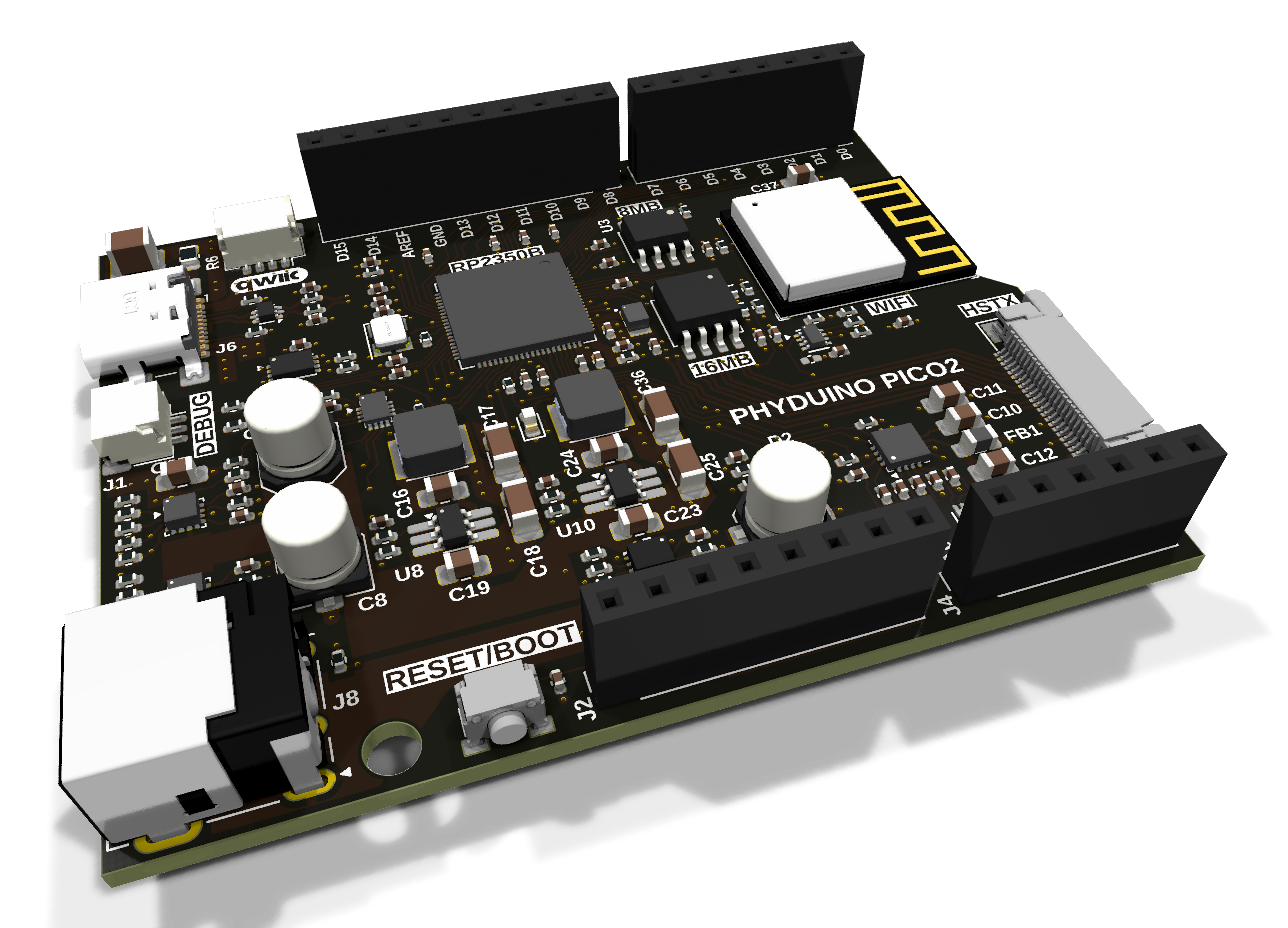
Project site: https://perc-sw.github.io/phyduino_pico2 (schematic, interactive BOM, PCB drawings, 3D model and datasheets)
Status: Rev A0 prototype (October 2026).
| Path | Contents |
|---|---|
phyduino_pico2.kicad_pro | KiCad project (net classes, design rules, DRC exclusions) |
phyduino_pico2.kicad_sch | Root schematic: headers and connectors, with the Microcontroller, Power and Wireless Communication sub-sheets |
phyduino_pico2_mcu.kicad_sch | Microcontroller: RP2350, crystal and debug connector, with two sub-sheets |
phyduino_pico_memory.kicad_sch | Memory: QSPI flash, PSRAM and the RESET/BOOT button controller |
phyduino_pico_peripherals.kicad_sch | Peripherals: ADC, EEPROM and I²C GPIO expander |
phyduino2_power_regs.kicad_sch | Power: eFuses, power mux and buck regulators |
phyduino_pico2_wifi.kicad_sch | Wireless Communication: ESP32-C6 module |
phyduino_pico2.kicad_pcb | 4-layer PCB |
scripts/ | Pre-release check: documentation links, generated outputs, part numbers and pinout against the design |
ibom.config.ini | Settings for the student interactive BOM (InteractiveHtmlBom plugin) |
fabrication/ | Gerber and drill files |
docs/ | Project site: schematic and PCB PDFs, interactive BOMs, 3D models, datasheets and design reviews |
The design files are in KiCad 10 format and can't be opened with earlier versions.
Some symbols and footprints come from the maintainer's own libraries, which aren't in this repository. KiCad may report these as missing library links. The board and schematic still open and plot correctly, because every footprint and symbol is stored in the design files.
The board's silkscreen and copper text use Liberation Sans, Tekton, Centaur and Photograph Signature. Install the fonts in .github/workflows/fonts/ so the text renders as it does on the fabricated board.
Released under the GNU General Public License v3.0. See LICENSE.
University of Toronto, Department of Physics: Electronics Support Services
| Qty | Value | Footprint | References |
|---|---|---|---|
| 25 | 0.1µF | Capacitor_SMD:C_0402_1005Metric | C1, C13, C110, C111, C117, C119, C125, C126, C127, C128, C129, C130, C131, C132, C133, C135 +9 |
| 22 | TestPoint_Small | Component - Test point SMT [UL]:TestPoint_SameSky_CPG-47-TH-B | TP1, TP2, TP3, TP10, TP11, TP12, TP13, TP14, TP15, TP16, TP17, TP18, TP19, TP20, TP22, TP23 +6 |
| 20 | 10kΩ | Resistor_SMD:R_0402_1005Metric | R20, R21, R22, R44, R45, R49, R51, R136, R137, R153, R157, R158, R162, R163, R164, R166 +4 |
| 9 | 5.1kΩ | Resistor_SMD:R_0402_1005Metric | R42, R43, R47, R48, R50, R55, R61, R62, R65 |
| 7 | 1000pF | Capacitor_SMD:C_0402_1005Metric | C30, C31, C32, C33, C35, C38, C59 |
| 4 | 10µF | Capacitor_SMD:C_0805_2012Metric_Pad1.18x1.45mm_HandSolder | C19, C23, C27, C37 |
| 4 | 1µF | Capacitor_SMD:C_0805_2012Metric_Pad1.18x1.45mm_HandSolder | C10, C11, C12, C134 |
| 4 | 22µF | Capacitor_SMD:C_1206_3216Metric_Pad1.33x1.80mm_HandSolder | C17, C18, C25, C36 |
| 4 | 4.7µF | Capacitor_SMD:C_0402_1005Metric | C2, C3, C4, C120 |
| 3 | 1.1kΩ | Resistor_SMD:R_0402_1005Metric | R46, R139, R156 |
| 3 | 100µF | Capacitor_SMD:C_Elec_5x5.4 | C8, C22, C28 |
| 3 | 27Ω | Resistor_SMD:R_0402_1005Metric | R3, R4, R5 |
| 3 | 42.2kΩ | Resistor_SMD:R_0402_1005Metric | R134, R135, R138 |
| 2 | 0.1µF | Capacitor_SMD:C_0805_2012Metric_Pad1.18x1.45mm_HandSolder | C16, C24 |
| 2 | 1.0kΩ | Component - Resistor Network:RESCAV50P200X100X55-8N | RN1, RN2 |
| 2 | 100pF | Capacitor_SMD:C_0402_1005Metric | C5, C7 |
| 2 | 100Ω | Resistor_SMD:R_0402_1005Metric | R1, R2 |
| 2 | 1nF | Capacitor_SMD:C_0402_1005Metric | C136, C141 |
| 2 | 215kΩ | Resistor_SMD:R_0402_1005Metric | R146, R155 |
| 2 | 27pF | Capacitor_SMD:C_0402_1005Metric | C14, C15 |
| 2 | 53.6kΩ | Resistor_SMD:R_0402_1005Metric | R150, R154 |
| 2 | 732kΩ | Resistor_SMD:R_0402_1005Metric | R143, R149 |
| 2 | AP63301WU-7 | Package_TO_SOT_SMD:TSOT-23-6_HandSoldering | U8, U10 |
| 2 | PPPC081LFBN-RC | Connector_PinSocket_2.54mm [KL]:PinSocket_1x08_P2.54mm_Vertical | J2, J5 |
| 2 | TPS259470ARPWR | Package - QFN [UL]:Texas_Instruments_VQFN-HR-10 | U6, U13 |
| 1 | 0.1µF | Capacitor_SMD:C_1210_3225Metric | C9 |
| 1 | 100kΩ | Resistor_SMD:R_0402_1005Metric | R165 |
| 1 | 10µH | Component - Inductor SMT [UL]:L_Bourns_SRP4021HMCT | L2 |
| 1 | 158kΩ | Resistor_SMD:R_0402_1005Metric | R58 |
| 1 | 196kΩ | Resistor_SMD:R_0402_1005Metric | R56 |
| 1 | 1977067-1 | Mechanical - Switch [UL]:TE_1977067-1 | SW1 |
| 1 | 1kΩ@100MHz | Inductor_SMD:L_0805_2012Metric_Pad1.05x1.20mm_HandSolder | FB1 |
| 1 | 1µF | Capacitor_SMD:C_0402_1005Metric | C39 |
| 1 | 220kΩ | Resistor_SMD:R_0805_2012Metric_Pad1.20x1.40mm_HandSolder | R6 |
| 1 | 22kΩ | Resistor_SMD:R_0402_1005Metric | R151 |
| 1 | 3.3µH | Component - Inductor SMT [UL]:L_Abracon_AOTA-B201610S | L3 |
| 1 | 3.6V | Diode_SMD:D_SOD-323 | D2 |
| 1 | 30kΩ | Resistor_SMD:R_0402_1005Metric | R59 |
| 1 | 3300pF | Capacitor_SMD:C_0402_1005Metric | C140 |
| 1 | 33kΩ | Resistor_SMD:R_0402_1005Metric | R152 |
| 1 | 4700pF | Capacitor_SMD:C_0402_1005Metric | C58 |
| 1 | 54-00127 | Conector - Power [UL]:TENSILITY_54-00127 | J8 |
| 1 | 6.8µH | Component - Inductor SMT [UL]:L_Bourns_SRP4021HMCT | L1 |
| 1 | 620Ω | Resistor_SMD:R_0402_1005Metric | R13 |
| 1 | 62kΩ | Resistor_SMD:R_0402_1005Metric | R57 |
| 1 | ABM8G-12.000MHZ-18-D2Y-T | Crystal [KL]:Crystal_SMD_Abracon_ABM8AIG-4Pin_3.2x2.5mm | Y1 |
| 1 | ADS7038IRTER | Package - QFN [UL]:QFN50P300X300X80-17N | U5 |
| 1 | AT24C64D-MAHM-T | Package - DFN [UL]:DFN-8-1EP_3x2mm_P0.5mm_EP1.3x1.4mm | U7 |
| 1 | AT25QF128A-SHB-T | Package_SO:SOIC-8_5.3x5.3mm_P1.27mm | U2 |
| 1 | ESP32-C6-MINI-1-H4 | Module - Espressif [UL]:ESP32-C6-MINI-1 | U11 |
| 1 | F32Q-1A7H1-11022 | Connector_FFC-FPC [KL]:Amphenol_F32Q-1A7x1-11022_1x22-1MP_P0.5mm_Horizontal | J7 |
| 1 | FXL6408UMX | Package - QFN [UL]:QFN40P260X180X55-16N | U14 |
| 1 | GREEN | LED_SMD:LED_0603_1608Metric | D1 |
| 1 | IS66WVS8M8FBLL-104NLI | Package_SO:SOIC-8_3.9x4.9mm_P1.27mm | U3 |
| 1 | LOGO | Drawings library [UL]:qwiic_6mm | G*** |
| 1 | MPZ1005S221HT000 | Inductor_SMD:L_0402_1005Metric | FB100 |
| 1 | MountingHole | MountingHole:MountingHole_3.2mm_M3 | H2 |
| 1 | PPPC061LFBN-RC | Connector_PinSocket_2.54mm [KL]:PinSocket_1x06_P2.54mm_Vertical | J4 |
| 1 | PPPC101LFBN-RC | Connector_PinSocket_2.54mm [KL]:PinSocket_1x10_P2.54mm_Vertical | J3 |
| 1 | RP2350B | Package_DFN_QFN [KL]:QFN-80-1EP_10x10mm_P0.4mm_EP3.4x3.4mm | U1 |
| 1 | SM03B-SRSS-TB | Connector_JST [KL]:JST_SH_SM03B-SRSS-TB_1x03-1MP_P1.00mm_Horizontal | J1 |
| 1 | SM04B-SRSS-TB | Connector_JST:JST_SH_SM04B-SRSS-TB_1x04-1MP_P1.00mm_Horizontal | J9 |
| 1 | TPS2121RUXR | Package - QFN [UL]:VQFN-HR-12 | U108 |
| 1 | TPS3424C11EF2ADRLR | Pacakge - SOT [UL]:SOT-5x3_DRL0008A_TEX | U15 |
| 1 | USB4110-GF-A | Connector - PC SMT [UL]:GCT-USBC-GCT_USB4110 | J6 |
| 1 | USBLC6-2P6 | Package_TO_SOT_SMD:SOT-666 | U9 |
The 176 most common of 179 parts.
It measures 68.6 × 53.3 mm and has 4 copper layers, 1.62 mm thick.
179 parts, built around the RP2350B, ESP32-C6-MINI-1-H4, ADS7038IRTER and AT25QF128A-SHB-T. The full list of its parts is on this page, with links to each part's symbol and footprint where PCBKit's library has them.
From the perc-sw/phyduino_pico2 repository on GitHub, at the commit this page was made from: the board is phyduino_pico2.kicad_pcb and its schematic phyduino2_power_regs.kicad_sch. PCBKit opens the board in the browser, with nothing to install.
Its repository publishes it under the GPL-3.0 licence: you may reuse it on that licence's terms (keep the author's notice, and for a copyleft licence share your changes alike).


TENNLab-UTK/NWRIST
Code and KiCAD PCB design for the NWRIST: Neuromorphic Wearable for Real-Time Intelligent Sensing Technology paper

sbarisic/MagMouse
Open source hall-effect based mouse - no mechanical contacts - no failure points


NessieCircuits/Riotee_Board
The Riotee board is a development board for battery-free wireless devices. The on-board wireless microcontroller runs off energy harvested from, for example, a solar panel and uses only tiny capacitors as energy…
