2 layers37 × 70.9 mm
Opendiag
maximus64/opendiag-hardware
OpenDIAG - Open Source OBD2 Interface (Hardware)
148 parts5CERN-OHL-S-2.0

 padamsarda/MT_test_driver-PCB
magnetorquer driver PCB for simulations and selection
MT test driver is an open-source printed circuit board by padamsarda, from the padamsarda/MT_test_driver-PCB repository on GitHub. It is a 2-layer board of 71.2 × 46.5 mm with 76 parts on 79 nets, routed with 382 tracks and 100 vias.
It is built around the TJA1051T/3/1, DRV8871DDA and AMS1117-3.3, with the USBLC6-2SC6 and NUP2105L among its other parts. Its parts include 24 capacitors, 15 resistors, 7 connectors, 6 ICs and 3 diodes. It belongs with the STM32 boards of this library.


A 2 layer test board for characterizing magnetorquer coils under different operating conditions like voltage, current & temperature.The coils are driven by a DRV8871 motor driver controlled by an STM32F4 mcu. The board integrates current and voltage monitoring while providing I²C and CAN interfaces for connecting external sensors such as magnetometers and temperature sensors. USB type C and SWD interfaces are provided for power, programming and debugging.
| MCU | STM32F405RGTx (Cortex-M4, LQFP-64) |
| Motor Driver | DRV8871DDA H-Bridge Driver |
| Current Sensing | INA219AID |
| Communication | CAN (TJA1051T/3) + I²C |
| Power Input | USB Type-C and DC Barrel Jack |
| Programming | SWD |
| Designed with | KiCad 10 |
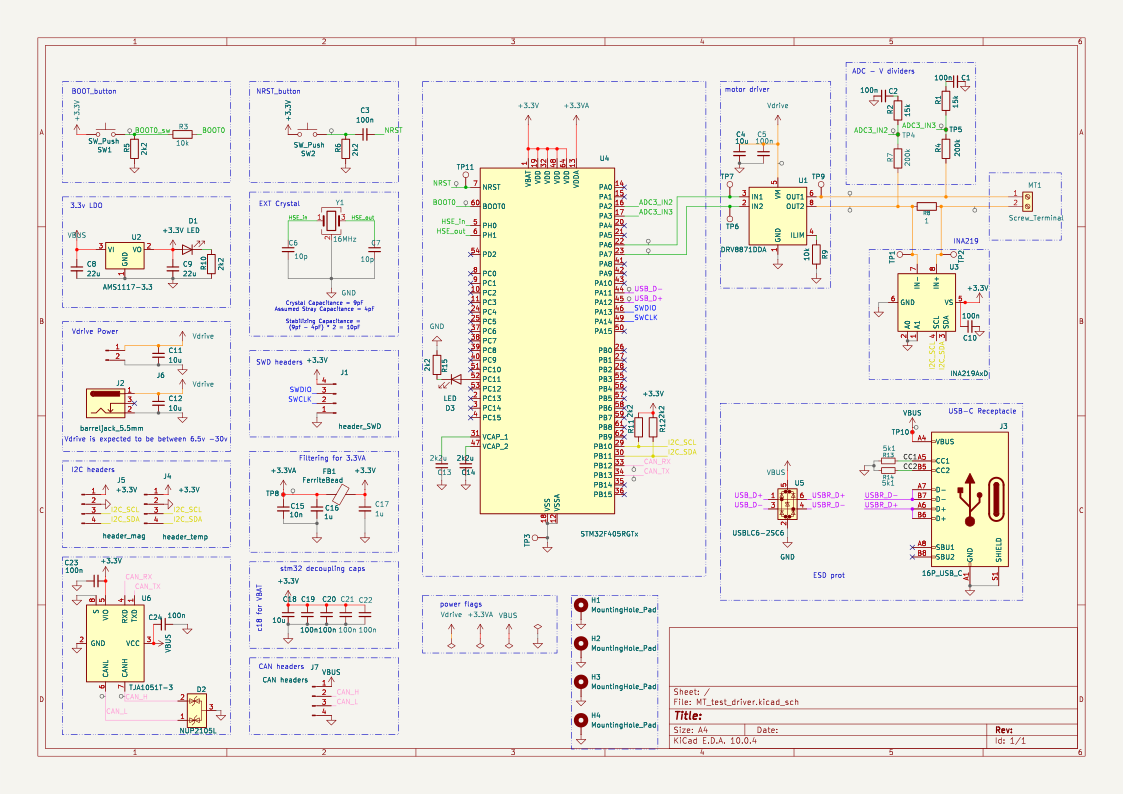
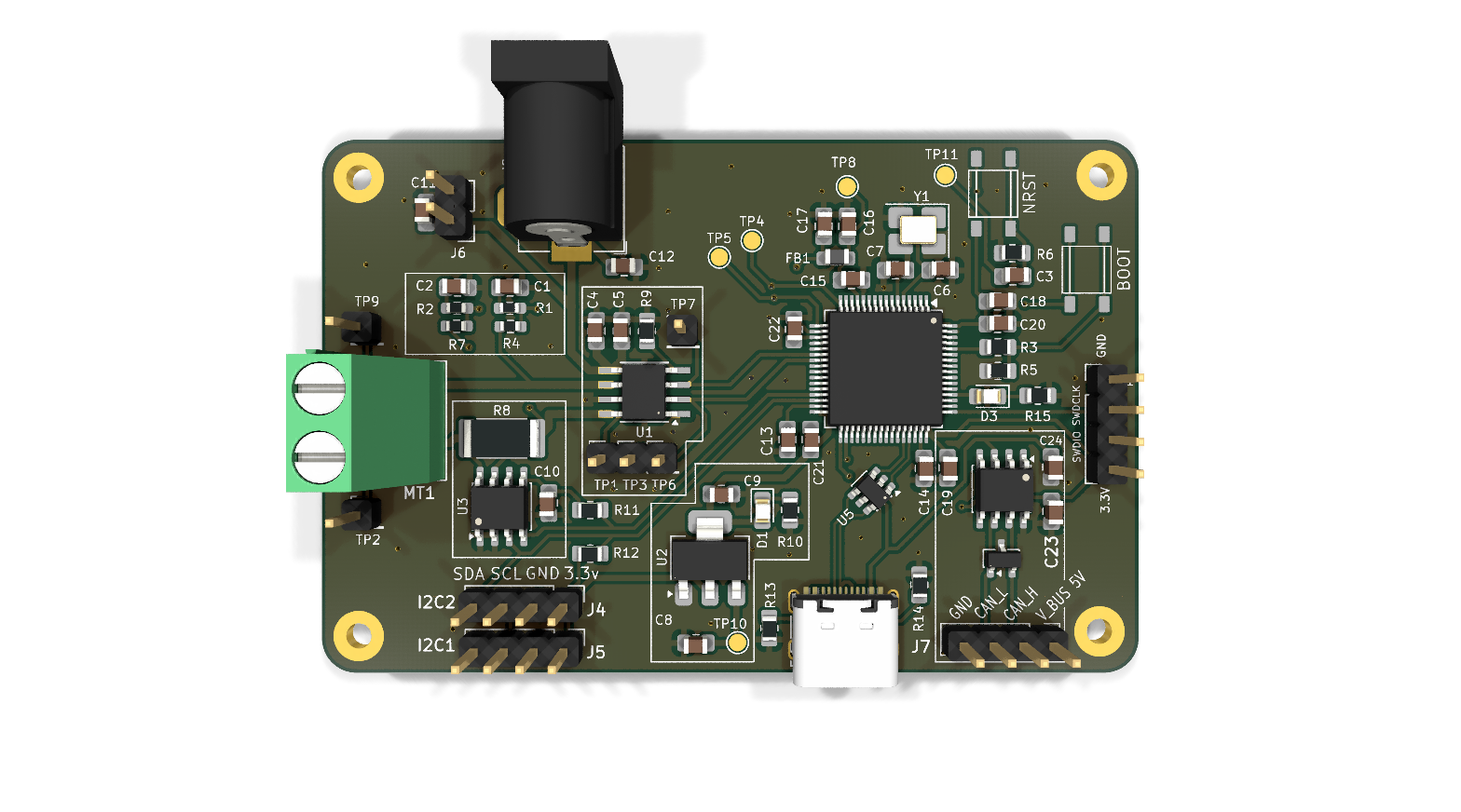
| Reference | Part | Function |
|---|---|---|
| U1 | DRV8871DDA | H-Bridge motor driver for magnetorquer coils |
| U2 | AMS1117-3.3 | 3.3 V linear voltage regulator |
| U3 | INA219AID | High-side current and power monitor |
| U4 | STM32F405RGTx | ARM Cortex-M4 microcontroller |
| U5 | USBLC6-2SC6 | USB ESD protection |
| U6 | TJA1051T/3 | CAN transceiver |
| Y1 | 16 MHz Crystal | MCU system clock |
| FB1 | Ferrite Bead | Power supply noise filtering |
| D2 | NUP2105L | CAN bus ESD protection |
| Reference | Interface | Description |
|---|---|---|
| J1 | SWD | Programming and debugging |
| J2 | DC Barrel Jack | External power input |
| J3 | USB Type-C | USB power input |
| J4 | Temperature Header | External temperature sensor interface |
| J5 | Magnetometer Header | I²C interface for external magnetometers |
| J6 | Battery Header | Battery connection |
| J7 | CAN Header | CAN communication interface |
| MT1 | Screw Terminal | Magnetorquer coil output |
Designed and developed as part of Team Anant.
| Qty | Value | Footprint | References |
|---|---|---|---|
| 11 | 100n | Capacitor_SMD:C_0805_2012Metric_Pad1.18x1.45mm_HandSolder | C1, C2, C3, C5, C10, C19, C20, C21, C22, C23, C24 |
| 6 | 2k2 | Resistor_SMD:R_0805_2012Metric_Pad1.20x1.40mm_HandSolder | R5, R6, R10, R11, R12, R15 |
| 6 | TestPoint | Connector_PinHeader_2.54mm:PinHeader_1x01_P2.54mm_Vertical | TP1, TP2, TP3, TP6, TP7, TP9 |
| 4 | 10u | Capacitor_SMD:C_0805_2012Metric_Pad1.18x1.45mm_HandSolder | C4, C11, C12, C18 |
| 4 | MountingHole_Pad | MountingHole:MountingHole_2.2mm_M2_Pad | H1, H2, H3, H4 |
| 4 | TestPoint_Small | TestPoint:TestPoint_Pad_D1.5mm | TP4, TP5, TP8, TP10 |
| 2 | 10k | Resistor_SMD:R_0805_2012Metric_Pad1.20x1.40mm_HandSolder | R3, R9 |
| 2 | 10p | Capacitor_SMD:C_0805_2012Metric_Pad1.18x1.45mm_HandSolder | C6, C7 |
| 2 | 15k | Resistor_SMD:R_0603_1608Metric_Pad0.98x0.95mm_HandSolder | R1, R2 |
| 2 | 1u | Capacitor_SMD:C_0805_2012Metric_Pad1.18x1.45mm_HandSolder | C16, C17 |
| 2 | 200k | Resistor_SMD:R_0603_1608Metric_Pad0.98x0.95mm_HandSolder | R4, R7 |
| 2 | 22u | Capacitor_SMD:C_0805_2012Metric_Pad1.18x1.45mm_HandSolder | C8, C9 |
| 2 | 2k2u | Capacitor_SMD:C_0805_2012Metric_Pad1.18x1.45mm_HandSolder | C13, C14 |
| 2 | 5k1 | Resistor_SMD:R_0805_2012Metric_Pad1.20x1.40mm_HandSolder | R13, R14 |
| 2 | LED | LED_SMD:LED_0805_2012Metric_Pad1.15x1.40mm_HandSolder | D1, D3 |
| 2 | SW_Push | Library:tactile switch 4.5_4.5 | SW1, SW2 |
| 1 | 1 | Resistor_SMD:R_2512_6332Metric_Pad1.40x3.35mm_HandSolder | R8 |
| 1 | 10n | Capacitor_SMD:C_0805_2012Metric_Pad1.18x1.45mm_HandSolder | C15 |
| 1 | 16MHz | Crystal:Crystal_SMD_3225-4Pin_3.2x2.5mm_HandSoldering | Y1 |
| 1 | 16P_USB_C | Connector_USB:USB_C_Receptacle_G-Switch_GT-USB-7010ASV | J3 |
| 1 | AMS1117-3.3 | Package_TO_SOT_SMD:SOT-223-3_TabPin2 | U2 |
| 1 | CAN headers | Connector_PinHeader_2.54mm:PinHeader_1x04_P2.54mm_Vertical | J7 |
| 1 | DRV8871DDA | Package_SO:Texas_HTSOP-8-1EP_3.9x4.9mm_P1.27mm_EP2.95x4.9mm_Mask2.4x3.1mm_ThermalVias | U1 |
| 1 | FerriteBead | Inductor_SMD:L_0805_2012Metric_Pad1.05x1.20mm_HandSolder | FB1 |
| 1 | INA219AxD | Package_SO:SOIC-8_3.9x4.9mm_P1.27mm | U3 |
| 1 | LOGO | LOGO | G*** |
| 1 | NUP2105L | Package_TO_SOT_SMD:SOT-23 | D2 |
| 1 | STM32F405RGTx | Package_QFP:LQFP-64_10x10mm_P0.5mm | U4 |
| 1 | Screw_Terminal | TerminalBlock_Phoenix:TerminalBlock_Phoenix_MKDS-1,5-2-5.08_1x02_P5.08mm_Horizontal | MT1 |
| 1 | TJA1051T-3 | Package_SO:SOIC-8_3.9x4.9mm_P1.27mm | U6 |
| 1 | TestPoint | TestPoint:TestPoint_Pad_D1.5mm | TP11 |
| 1 | USBLC6-2SC6 | Package_TO_SOT_SMD:SOT-23-6 | U5 |
| 1 | barreljack_5.5mm | Connector_BarrelJack:BarrelJack_Horizontal | J2 |
| 1 | header_SWD | Connector_PinHeader_2.54mm:PinHeader_1x04_P2.54mm_Vertical | J1 |
| 1 | header_battery | Connector_PinHeader_2.54mm:PinHeader_1x02_P2.54mm_Vertical | J6 |
| 1 | header_mag | Connector_PinHeader_2.54mm:PinHeader_1x04_P2.54mm_Vertical | J5 |
| 1 | header_temp | Connector_PinHeader_2.54mm:PinHeader_1x04_P2.54mm_Vertical | J4 |
maximus64/opendiag-hardware
OpenDIAG - Open Source OBD2 Interface (Hardware)


romioRN/Dash6.8-hardware
wifi name "service", password 12345678, connect to 192.167.4.1

akhilveeraghanta/the-bots-mainboard
The main board for the the bots SSL robocup team

KazanNinja/MM36-Data-Hub
ESP32 based DAQ board. Fit with a 4 external 16bit 5V capable ADCs, 6-DOF IMU, and GPS breakout. Has two 5V > 3.3V & 12V > 3.3V voltage dividers

CanGulmez/BLDC-Motor-Driver
2kW BLDC Motor Driver Firmware Development and KiCAD design

danielsimonreinhardt/microHIL
microHIL is a self-developed testing device for setting up a basic hardware-in-the-loop environment

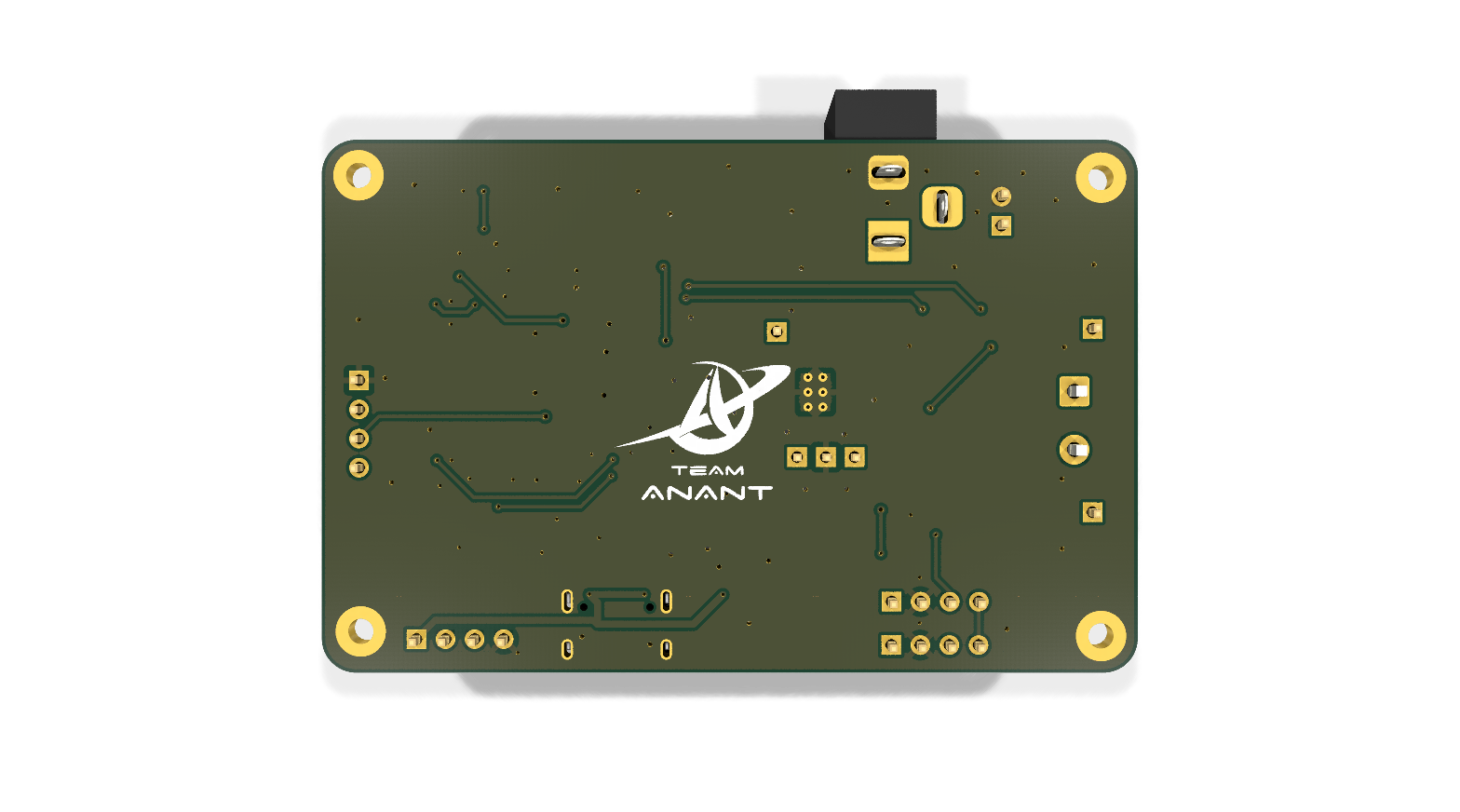
It measures 71.2 × 46.5 mm and has 2 copper layers, 1.6 mm thick.
76 parts, built around the TJA1051T/3/1, DRV8871DDA, AMS1117-3.3 and USBLC6-2SC6. The full list of its parts is on this page, with links to each part's symbol and footprint where PCBKit's library has them.
From the padamsarda/MT_test_driver-PCB repository on GitHub, at the commit this page was made from: the board is MT_test_driver.kicad_pcb and its schematic MT_test_driver.kicad_sch. PCBKit opens the board in the browser, with nothing to install.
Its repository states no licence, so its author keeps all rights: ask padamsarda before reusing the design.