4 layers66.8 × 38 mm

 m4rkw/l0destar43
l0destar open-source tracker project
L0destar is an open-source printed circuit board by m4rkw, from the m4rkw/l0destar repository on GitHub. It is a 2-layer board of 115.2 × 78.6 mm with 164 parts on 152 nets, routed with 1,410 tracks and 192 vias.
It is built around the TJA1051T/3/1, L9637D and LM66100DCK, with the BAT54S, SMBJ30A and 1N4148W among its other parts. Its parts include 135 switches and 2 capacitors.


NOTE: THIS HAS NOT YET BEEN BUILT OR TESTED, USE AT YOUR OWN RISK
This is a prototype, not a product. Nothing here is validated or certified, the parts lists are examples rather than a verified BOM, and every number below is a desk calculation from datasheets rather than a bench measurement - repeat the testing yourself rather than taking any of it on trust.
I strongly recommend not using unbranded CR123 cells or buying them from less reputable sources.
Before building or installing anything from this repository, read the full disclaimer.
| Item | Test | Result | Notes |
|---|---|---|---|
| Input stage | 12V car input reverse polarity | NOT TESTED | S1U1/S1Q1 ideal diode blocks; S1Z1 conducts forward into S1F1, which should clear |
| Input stage | Pass-through drop VCAR to PPTRACKER at 50 mA and 250 mA | NOT TESTED | Expected tens of mV through S1Q1 (27 mΩ), with brief body-diode drops while the LM74610 charge pump recharges |
| Input stage | ISO 7637-2 pulse 2a and 35V load dump ride-through | NOT TESTED | S1Z1 is the tracker's 33V TVS; S1C2 47 µF + S1C6 10 µF + S1C1 on VCAR |
| Switchover | Boost enables when the car rail falls below ~10.06V | NOT TESTED | S5U1 with the 6.8M/909k divider |
| Switchover | Boost disables when the car rail returns above ~11V | NOT TESTED | Depends on the cell voltage through S5R38/S5R39, see Notes |
| Switchover | PPTRACKER dip during handover under a forced LTE burst | NOT TESTED | Scope on J2 pin 4; S1C4 100 µF + S1C5 10 µF carry the gap |
| Boost | 9.6V output at S4C14/S4C15 | NOT TESTED | 1.202V x (1 + 909k/130k) = 9.61V; ~9V at J2 after S1D2 |
| Boost | Output current at a 2.5V cell | NOT TESTED | Burst Mode limits to ~190 mA at 2.5V in, ~300 mA at 3V in (datasheet curves) |
| Boost | Bode plot and load step | NOT TESTED | Compensation is the datasheet 2xAA to 12V example, not tuned for this operating point |
| Cell lockout | Boost held off below 2.45V, released above 2.52V | NOT TESTED | S5U4 with 1M/1M divider and 33M feedback; test on a bench supply in place of the cell |
| Cell lockout | Re-enable paced ~0.3 s | NOT TESTED | S5R41/S5C7; S5D1 makes the disable immediate |
| Cell | Reversed cell is harmless | NOT TESTED | S3U1 blocks, VBAT sits at 0V, no backup |
| Cell | No current ever flows into the cell | NOT TESTED | Ammeter in series with the cell with the car present and during handover |
| Wake pulse | IGN pulse at boost start | NOT TESTED | Expected ~12V peak, above 8V for ~0.4 s, at J2 pin 5 |
| Wake pulse | Sleeping tracker wakes and raises backup power | NOT TESTED | Needs firmware with CONFIG_APP_BACKUP_SUPPLY=y |
| Board | Idle draw from the cell, tracker asleep | NOT TESTED | Expected ~280 µA at a 2.9V cell |
| Board | Parked drain from the car with the cell fitted | NOT TESTED | Expected ~1.6 µA from the 7.7M sense divider on top of the tracker's own draw |
| Enclosure | Board and cell fit, lid clearance over the cell | NOT TESTED | 1.9 mm above the cell by the datasheet, see enclosure/ |
A non-rechargeable cell rather than a rechargeable pack, for three reasons:
The cell is a consumable. A backup power alert that runs for a long time
means the cell needs replacing, since it does not recover. Taking the cell
out is the storage mode.
A sleeping tracker has three wake sources: its timer, the accelerometer and ignition-present. A power cut touches none of them, so on its own it would be found at the next timed wake. The module therefore fakes ignition for a moment when it takes over.
The tracker's wake is level-triggered and the firmware latches it, so the
pulse only has to trip the interrupt. On an ignition wake the firmware reads
the rail first: in the backup band it is the module's pulse, so the unit
reports at once with the backup power alert and goes back to sleep.
Limits: a second cut within the ~40 s VBOOST decay, or a cut with the key on and the ignition wire loaded by the car, gives no pulse; both fall back to the timed wake.
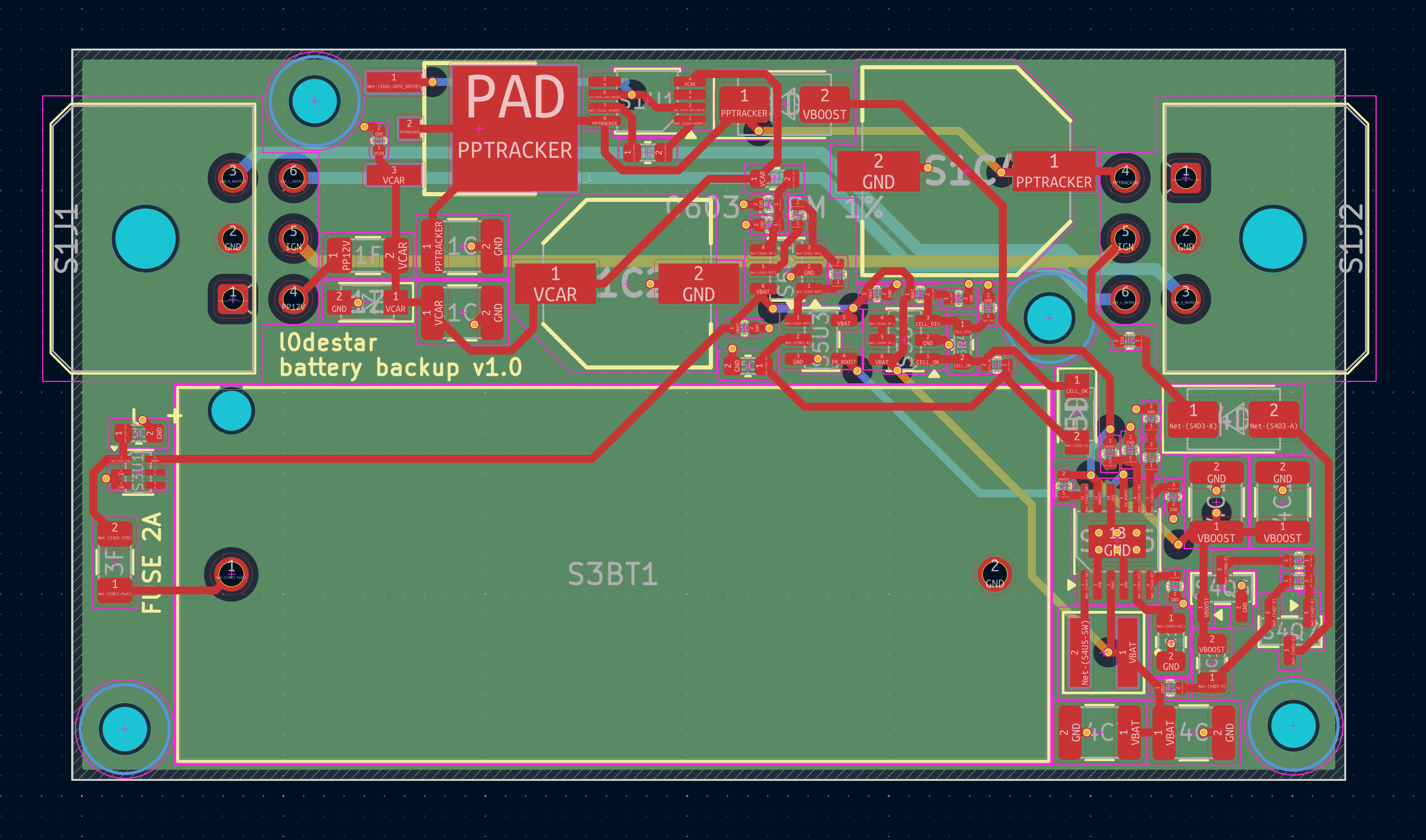
Both connectors are the tracker's Molex Micro-Fit 3.0 2x3 (43045-0600) with the v3.4 pinout. J1 is the car harness, J2 goes to the tracker.
| Pin | J1 (car) | J2 (tracker) | Notes |
|---|---|---|---|
| 1 | SPARE | SPARE | Unused by v3.4, not connected on this board |
| 2 | GND | GND | |
| 3 | CAN_H / K | CAN_H / K | Passed straight through |
| 4 | +12V | +12V (PPTRACKER) | Car through the ideal diode, or ~9V from the boost on backup |
| 5 | IGN | IGN | Passed straight through; the wake pulse is injected here |
| 6 | CAN_L / L | CAN_L / L | Passed straight through |
The tracker needs CONFIG_APP_BACKUP_SUPPLY=y. With it, a supply between
CONFIG_APP_BACKUP_MIN_MV (8500) and CONFIG_APP_BACKUP_MAX_MV (9700) with
the ignition off is treated as backup power rather than a flat car battery:
timed reports keep going, the 11.8V power-off and 12.0V sleep-safety rules
are bypassed, a backup power alert is raised once and a car power restored alert when the rail comes back. Without the module a car battery in
that band is flat, so leave it off on trackers that do not have one.
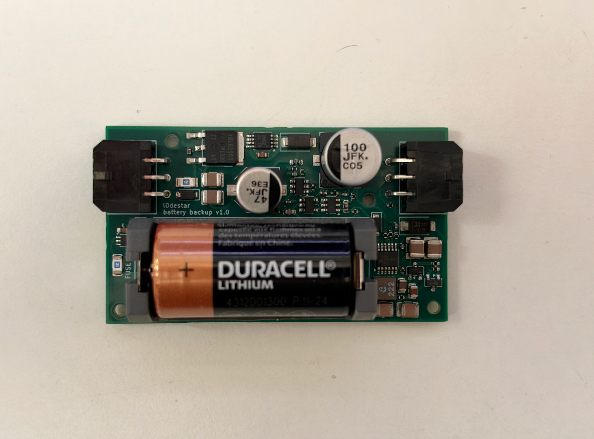
The board carries a Keystone 1051 CR123A holder and nothing else as a cell input. Fit a CR123A from one of the three big brands (Energizer 123 / EL123AP, Panasonic CR123A, Duracell DL123A): all are high-rate Li-MnO2 cells, 1500-1550 mAh, rated for the ~130 mA typical / ~250 mA worst-case bursts the boost draws. Mark polarity on the silk and the lid; a reversed cell is harmless but gives no backup.
Other primary chemistries (a 4.1V Tadiran TLM for installs above 60 °C, a C-size Li-SOCl2 for long runtime) are not stuffing options on this board: neither fits the CR123A holder, a 4.1V cell exceeds the AND gate's 3.6V supply limit and needs a different lockout divider, and Li-SOCl2 wants a depassivation bleed. Either is a sheet 2 change.
endpoint_off_grid warnings
are cosmetic| Item | Description | Specification | Example | Notes |
|---|---|---|---|---|
| S1J1 | Car harness connector | Molex Micro-Fit 3.0 2x03 43045-0600 | 43045-0600 | |
| S1J2 | Tracker harness connector | Molex Micro-Fit 3.0 2x03 43045-0600 | 43045-0600 | |
| S1F1 | 2A fuse, car input | 1206 2A time-lag | 0407002.WRA | Time-lag, same as tracker S2F1/S2F2 |
| S1Z1 | 33V TVS diode | PTVS33VS1UTR,115 SOD-123W | PTVS33VS1UTR,115 | Do not lower the standoff, see Notes |
| S1U1 | Smart diode controller | LM74610-Q1 VSSOP-8 | LM74610QDGKRQ1 | Zero Iq, floating |
| S1Q1 | Ideal diode MOSFET | IRLR2905 DPAK, 55V, 27 mΩ | IRLR2905TRPBF | Backordered at DigiKey when checked, see Notes |
| S1D2 | OR-ing diode from VBOOST | S1B SMA, 100V 1A silicon | S1B-13-F | Silicon, not Schottky |
| S1C1 | 100nF capacitor | 0402 >= 50V 10% X7R | GRM155R71H104KE14D | |
| S1C2 | 47uF electrolytic, VCAR | 63V SMD, 105 °C | EEE-FK1J470P | |
| S1C3 | 2.2uF charge-pump capacitor | 0603 >= 25V 10% X7R | GRM188Z71E225KE43D | |
| S1C4 | 100uF electrolytic, PPTRACKER | 63V SMD, 105 °C | EEE-FK1J101P | |
| S1C5 | 10uF capacitor, PPTRACKER | 1210 >= 50V 10% X7R SOFT TERMINATION | MCJCU32MLB7106KPPDT1 | Flex-crack rule |
| S1C6 | 10uF capacitor, VCAR | 1210 >= 50V 10% X7R SOFT TERMINATION | MCJCU32MLB7106KPPDT1 | Flex-crack rule |
| S3BT1 | CR123A holder | Keystone 1051, through-hole | 1051 | Pin 1 is + |
| S3F1 | 2A fuse, cell | 1206 2A time-lag | 0407002.WRA | Not a PTC: the 2A 0ZCJ part is only rated 6V |
| S3U1 | Ideal diode | LM66100 SC70-6 | LM66100DCKR | Same part as tracker S11U1 |
| S3C1 | 2.2uF capacitor | 0603 >= 25V 10% X7R | GRM188Z71E225KE43D | |
| S4U5 | Boost converter | LTC3122EMSE MSOP-12-EP | LTC3122EMSE#PBF | Solder the exposed pad, it is PGND |
| S4L1 | Inductor | XFL4020-222ME 2.2uH | XFL4020-222MEC | Same part as tracker S6L1 |
| S4C7 | 47uF input capacitor | 1210 >= 10V 20% X7R | CL32B476MPJNNNE | Same part as tracker S11C1 |
| S4C8 | 47uF input capacitor | 1210 >= 10V 20% X7R | CL32B476MPJNNNE | |
| S4C9 | 100nF CAP pin capacitor | 0402 >= 50V 10% X7R | GRM155R71H104KE14D | CAP to VOUT |
| S4C11 | 560pF compensation capacitor | 0402 >= 50V 5% C0G/NP0 | Any 0402 560pF C0G | |
| S4C12 | 10pF compensation capacitor | 0402 >= 50V 5% C0G/NP0 | GRM1555C1H100JA01D | |
| S4C13 | 4.7uF VCC capacitor | 0805 >= 50V 10% X7R | GRM21BZ71H475KE15K | |
| S4C14 | 10uF output capacitor | 1210 >= 50V 10% X7R SOFT TERMINATION | MCJCU32MLB7106KPPDT1 | 50V rating keeps ~9 µF at 9.6V |
| S4C15 | 10uF output capacitor | 1210 >= 50V 10% X7R SOFT TERMINATION | MCJCU32MLB7106KPPDT1 | |
| S4R14 | Oscillator frequency resistor | 0402 57.6K 1% | Any 0402 57.6K 1% | 57.6K == 1MHz |
| S4R18 | Compensation resistor | 0402 200K 1% | Any 0402 200K 1% | |
| S4R19 | FB divider top | 0402 909K 1% ANTI-SULFUR AEC-Q200 | AF0402FR-07909KL | VOUT == 1.202V x (1 + S4R19/S4R20) == 9.61V, keep 1%, anti-sulfur required |
| S4R20 | FB divider bottom | 0402 130K 1% | Any 0402 130K 1% | Keep 1% |
| S4C17 | Wake pulse flying capacitor | 0805 >= 50V 10% X7R | GRM21BZ71H475KE15K | 50V part so it keeps ~4 µF at 12V bias |
| S4Q6 | Wake pulse switch | 2N7002 SOT-23 | 2N7002 | Any vendor |
| S4Q7 | Wake pulse high-side PNP | BC856B SOT-23 | BC856BLT1G | |
| S4D3 | Wake pulse isolation diode | S1B SMA, 100V 1A silicon | S1B-13-F | Silicon, not Schottky |
| S4R21 | Wake pulse series resistor | 0402 10K 5% | CRCW040210K0FKED | |
| S4R22 | Wake capacitor charge resistor | 0402 1M 1% | ERJ2RKF1004X | |
| S4R24 | Q7 base drive resistor | 0402 1M 1% | ERJ2RKF1004X | |
| S4R25 | Q7 base-emitter hold-off | 0402 1M 1% | ERJ2RKF1004X | |
| S5U1 | Car-rail sense comparator | TLV3012 SOT-23-6 | TLV3012AIDBVR | 1.242V reference, 2.8 µA |
| S5U4 | Cell lockout comparator | TLV3012 SOT-23-6 | TLV3012AIDBVR | |
| S5U3 | AND gate | SN74AUP1G08 SOT-23-5 | SN74AUP1G08DBVR | Schmitt inputs; do not substitute an LVC part |
| S5D1 | Pacing discharge diode | PMEG2010ER SOD-123W | PMEG2010ER,115 | |
| S5R32 | Car-rail divider top | 0603 6.8M 1% | Any 0603 6.8M 1% 75V | 0603 for the 75V rating |
| S5R33 | Car-rail divider bottom | 0402 909K 1% ANTI-SULFUR AEC-Q200 | AF0402FR-07909KL | Same part as S4R19; anti-sulfur not required here |
| S5R38 | Car-sense hysteresis | 0402 47K 5% | ERJ2RKF4702X | |
| S5R39 | Car-sense hysteresis feedback | 0402 1M 1% | ERJ2RKF1004X | |
| S5R36 | Cell lockout divider top | 0402 1M 1% | ERJ2RKF1004X | Keep 1%, sets 2.45V/2.52V with S5R37/S5R40 |
| S5R37 | Cell lockout divider bottom | 0402 1M 1% | ERJ2RKF1004X | Keep 1% |
| S5R40 | Cell lockout hysteresis | 0603 33M 5% | MCHVR03JTHX3305 | Same part as tracker S11R3 |
| S5R41 | Pacing resistor | 0402 1M 1% | ERJ2RKF1004X | With S5C7: ~0.3 s |
| S5C1 | IN- filter capacitor | 0402 >= 50V 5% C0G/NP0 | 0402N101J500CT | |
| S5C6 | IN+ filter capacitor | 0402 >= 50V 5% C0G/NP0 | 0402N101J500CT | |
| S5C2 | Comparator decoupling | 0402 >= 50V 10% X7R | GRM155R71H104KE14D | Place between S5U1 and S5U4 |
| S5C5 | AND gate decoupling | 0402 >= 50V 10% X7R | GRM155R71H104KE14D | |
| S5C7 | Pacing capacitor | 0603 220nF >= 50V 10% X7R | Any 0603 220nF 50V X7R | |
| - | CR123A cell | Li-MnO2 3.0V 1500-1550 mAh, branded | Energizer EL123AP / Panasonic CR123A / Duracell DL123A | Consumable; buy from a distributor |
Aggregated from the bill of materials above. Quantities are per board.
| Item | Quantity | Specification | Example | Notes |
|---|---|---|---|---|
| Molex Micro-Fit 3.0 2x03 PCB connector | 2 | 43045-0600 | 43045-0600 | |
| CR123A holder | 1 | Keystone 1051 | 1051 | |
| 2A fuse | 2 | 1206 2A time-lag | 0407002.WRA | 1x car input, 1x cell |
| 33V TVS diode | 1 | PTVS33VS1UTR,115 SOD-123W | PTVS33VS1UTR,115 | |
| S1B rectifier | 2 | SMA 100V 1A silicon | S1B-13-F | |
| PMEG2010ER Schottky | 1 | SOD-123W | PMEG2010ER,115 | |
| Smart diode controller | 1 | LM74610-Q1 VSSOP-8 | LM74610QDGKRQ1 | |
| N-channel MOSFET, DPAK | 1 | IRLR2905 55V 27 mΩ | IRLR2905TRPBF | See Notes for substitutes |
| Ideal diode | 1 | LM66100 SC70-6 | LM66100DCKR | |
| Boost converter | 1 | LTC3122EMSE MSOP-12-EP | LTC3122EMSE#PBF | |
| Nanopower comparator | 2 | TLV3012 SOT-23-6 | TLV3012AIDBVR | |
| AND gate | 1 | SN74AUP1G08 SOT-23-5 | SN74AUP1G08DBVR | |
| Inductor | 1 | XFL4020-222ME 2.2uH | XFL4020-222MEC | |
| 2N7002 MOSFET | 1 | SOT-23 | 2N7002 | |
| PNP transistor | 1 | BC856B SOT-23 | BC856BLT1G | |
| 47uF 63V electrolytic | 1 | SMD 105 °C | EEE-FK1J470P | |
| 100uF 63V electrolytic | 1 | SMD 105 °C | EEE-FK1J101P | |
| 10uF 1210 soft-termination capacitor | 4 | 1210 >= 50V 10% X7R SOFT TERMINATION | MCJCU32MLB7106KPPDT1 | |
| 47uF 1210 capacitor | 2 | 1210 >= 10V 20% X7R | CL32B476MPJNNNE | |
| 4.7uF 0805 capacitor | 2 | 0805 >= 50V 10% X7R | GRM21BZ71H475KE15K | |
| 2.2uF 0603 capacitor | 2 | 0603 >= 25V 10% X7R | GRM188Z71E225KE43D | |
| 220nF 0603 capacitor | 1 | 0603 >= 50V 10% X7R | Any 0603 220nF 50V X7R | |
| 100nF 0402 capacitor | 4 | 0402 >= 50V 10% X7R | GRM155R71H104KE14D | |
| 560pF 0402 capacitor | 1 | 0402 >= 50V 5% C0G/NP0 | Any 0402 560pF C0G | |
| 100pF 0402 capacitor | 2 | 0402 >= 50V 5% C0G/NP0 | 0402N101J500CT | |
| 10pF 0402 capacitor | 1 | 0402 >= 50V 5% C0G/NP0 | GRM1555C1H100JA01D | |
| 909K 0402 anti-sulfur resistor | 2 | 0402 909K 1% ANTI-SULFUR AEC-Q200 | AF0402FR-07909KL | S4R19 (required anti-sulfur), S5R33 |
| 1M 0402 resistor | 7 | 0402 1M 1% | ERJ2RKF1004X | |
| 130K 0402 resistor | 1 | 0402 130K 1% | Any 0402 130K 1% | |
| 200K 0402 resistor | 1 | 0402 200K 1% | Any 0402 200K 1% | |
| 57.6K 0402 resistor | 1 | 0402 57.6K 1% | Any 0402 57.6K 1% | |
| 47K 0402 resistor | 1 | 0402 47K 5% | ERJ2RKF4702X | |
| 10K 0402 resistor | 1 | 0402 10K 5% | CRCW040210K0FKED | |
| 6.8M 0603 resistor | 1 | 0603 6.8M 1% 75V | Any 0603 6.8M 1% 75V | |
| 33M 0603 resistor | 1 | 0603 33M 5% | MCHVR03JTHX3305 | |
| CR123A cell | 1 | Li-MnO2 3.0V, branded | Energizer EL123AP / Panasonic CR123A / Duracell DL123A | Consumable |
| M2 heat-set insert | 4 | Ø3.2 hole, 4.6 mm | - | Enclosure |
| M2 x 12 mm screw | 4 | - | - | Enclosure; 12 mm, not the tracker enclosure's 10 mm |
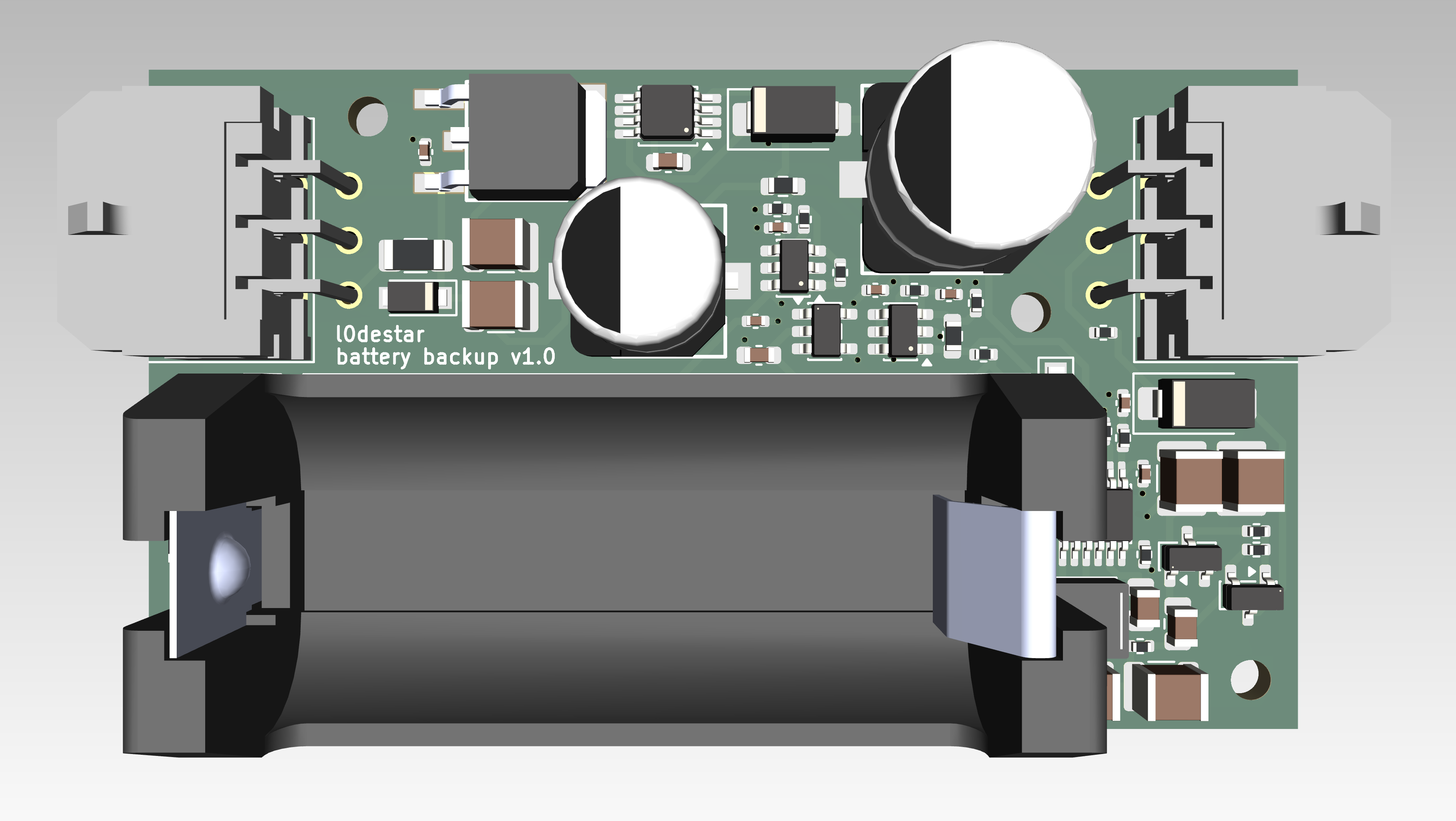
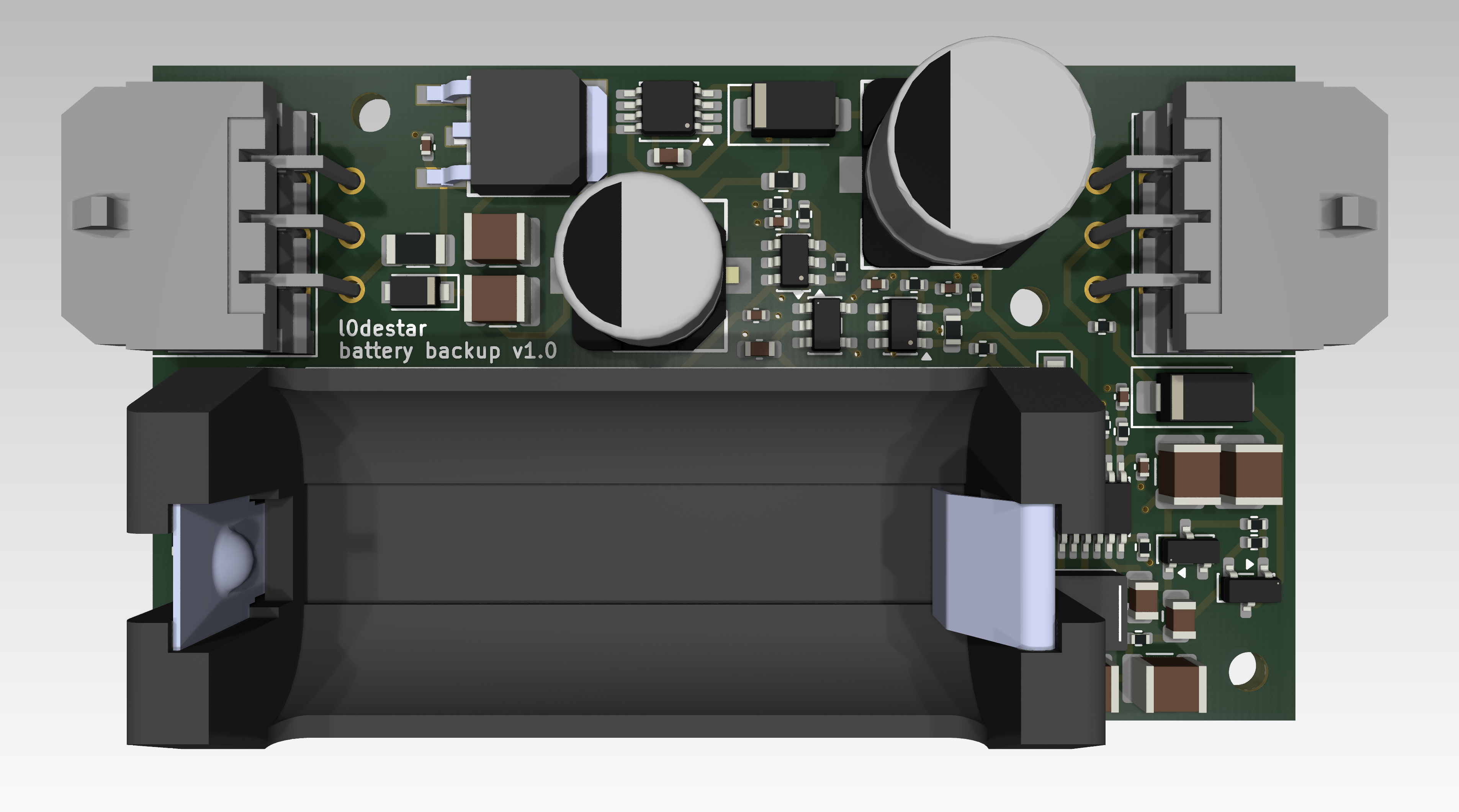
A 3D-printable two-part enclosure is in enclosure/: 68.9 x 42.0 x 31.0 mm outer, same construction as the v3.3 tracker enclosure (flat butt joint, M2 heat-set inserts in the top, screws in from underneath). The cell is accessible with the top removed. Print in PETG or ABS - PLA softens around 60 °C, which a parked car reaches. Unprinted and unvalidated; see its README.
| Qty | Value | Footprint | References |
|---|---|---|---|
| 22 | TestPoint | TestPoint:TestPoint_Pad_1.0x1.0mm | GND1, GND2, IGN_SENSE1, PP3V3, PP3V3_AUX1, PP3V3_CAN1, PP3V3_GPS1, PP3V3_RLY_FB1, PP12V_AUX1, PP12V1, PP12VI1, PP12VIP1, PP12VK1, PP12VP1, PP12VR1, PP12VS1 +6 |
| 20 | 10K | Resistor_SMD:R_0805_2012Metric | S2R1, S2R2, S5R2, S5R3, S5R5, S5R6, S7R5, S7R11, S10R9, S10R10, S11R2, S11R4, S11R6, S11R8, S11R10, S11R12 +4 |
| 15 | 100K | Resistor_SMD:R_0805_2012Metric | S1R3, S4R2, S5R1, S5R4, S6R9, S7R6, S7R8, S7R10, S7R12, S11R1, S11R3, S11R5, S11R7, S11R9, S11R11 |
| 9 | 100nF | Capacitor_SMD:C_0805_2012Metric | S3C2, S4C1, S6C2, S6C6, S9C1, S9C2, S9C5, S10C1, S10C2 |
| 9 | LM66100DCK | Package_TO_SOT_SMD:SOT-363_SC-70-6 | S5U1, S6U3, S9U3, S9U4, S10U3, S10U4, S10U5, S10U6, S15U1 |
| 6 | 2N7002 | Package_TO_SOT_SMD:SOT-23 | S4Q1, S5Q1, S5Q2, S7Q3, S7Q5, S10Q1 |
| 6 | BAT54S | Package_TO_SOT_SMD:SOT-23 | S11D1, S11D2, S11D3, S11D4, S11D5, S11D6 |
| 4 | 1uF | Capacitor_SMD:C_0805_2012Metric | S3C1, S6C3, S6C7, S15C4 |
| 4 | MountingHole | MountingHole:MountingHole_3.2mm_M3 | H1, H2, H3, H4 |
| 4 | SMBJ30A | Diode_SMD:D_SMB | S2D2, S2D4, S10D1, S10D2 |
| 3 | 1K | Resistor_SMD:R_0805_2012Metric | S1R4, S1R5, S1R6 |
| 3 | LED | LED_SMD:LED_0603_1608Metric | S1D1, S1D2, S1D3 |
| 2 | 100pF | Capacitor_SMD:C_0603_1608Metric | S15C1, S15C2 |
| 2 | 10pF | Capacitor_SMD:C_0805_2012Metric | S6C4, S6C9 |
| 2 | 10uF | Capacitor_SMD:C_0805_2012Metric | S9C6, S10C3 |
| 2 | 18.2K | Resistor_SMD:R_0805_2012Metric | S6R1, S6R4 |
| 2 | 1M | Resistor_SMD:R_0805_2012Metric | S6R3, S6R6 |
| 2 | 1N4148W | Diode_SMD:D_SOD-323 | S5D1, S5D2 |
| 2 | 22uF | Capacitor_SMD:C_0805_2012Metric | S6C5, S6C10 |
| 2 | 27pF | Capacitor_SMD:C_0603_1608Metric | S9C7, S9C8 |
| 2 | 4.7K | Resistor_SMD:R_0805_2012Metric | S1R1, S1R2 |
| 2 | 4.7uF | Capacitor_SMD:C_0805_2012Metric | S6C1, S6C8 |
| 2 | 56K | Resistor_SMD:R_0805_2012Metric | S4R1, S4R3 |
| 2 | AO3407A | Package_TO_SOT_SMD:SOT-23 | S2Q1, S2Q2 |
| 2 | BZX84C15 | Package_TO_SOT_SMD:SOT-23 | S2D1, S2D3 |
| 2 | LT8609AIMSE_PBF | libs:LT8609AIMSE | S6U1, S6U2 |
| 2 | XFL4020-222ME | libs:IND_XFL4020-222ME | S6L1, S6L2 |
| 1 | 10nF | Capacitor_SMD:C_0603_1608Metric | S15C3 |
| 1 | 15m (CSS2H-2512R-L150F) | Resistor_SMD:R_2512_6332Metric | S3R1 |
| 1 | 187K | Resistor_SMD:R_0805_2012Metric | S6R2 |
| 1 | 2200uF | Capacitor_SMD:CP_Elec_16x17.5 | C1 |
| 1 | 220uF | Capacitor_SMD:CP_Elec_8x6.9 | C2 |
| 1 | 226K | Resistor_SMD:R_0805_2012Metric | S6R5 |
| 1 | 47-100 nH, SRF > 2 GHz | Inductor_SMD:L_0603_1608Metric | S15L1 |
| 1 | 510R | Resistor_SMD:R_2512_6332Metric | S10R7 |
| 1 | 600R | Inductor_SMD:L_0603_1608Metric | S15FB1 |
| 1 | ABM8G-40.000MHZ-18-D2Y-T | Crystal:Crystal_SMD_3225-4Pin_3.2x2.5mm | S9Y1 |
| 1 | ASM330LHHXG1TR | Package_DIP:DIP-24_W15.24mm | S8U1 |
| 1 | Conn_01x20_Socket | libs:MakerDiary_nRF9151_ConnectKit_PinHeader_1-20 | S1J2 |
| 1 | Conn_01x20_Socket_21-40 | libs:MakerDiary_nRF9151_ConnectKit_PinHeader_21-40 | S1J3 |
| 1 | DMG3415U | Package_TO_SOT_SMD:SOT-23 | S7Q4 |
| 1 | DMP3098L | Package_TO_SOT_SMD:SOT-23 | S7Q6 |
| 1 | GPS_SMA | libs:SAMTEC_SMA-J-P-H-RA-TH1 | S15J2 |
| 1 | GPS_UFL | Connector_Coaxial:U.FL_Hirose_U.FL-R-SMT-1_Vertical | S15J1 |
| 1 | GSM_SMA | libs:SAMTEC_SMA-J-P-H-RA-TH1 | S15J4 |
| 1 | GSM_UFL | Connector_Coaxial:U.FL_Hirose_U.FL-R-SMT-1_Vertical | S15J3 |
| 1 | INA228 | Package_SO:TSSOP-10_3x3mm_P0.5mm | S3U1 |
| 1 | L9637D | Package_SO:SOIC-8_3.9x4.9mm_P1.27mm | S10U1 |
| 1 | MCP2518FD-xQBB | Package_SO:SOIC-14_3.9x8.7mm_P1.27mm | S9U2 |
| 1 | Main connector | Connector_Molex:Molex_Micro-Fit_3.0_43045-1400_2x07_P3.00mm_Horizontal | S1J1 |
| 1 | NUP2105L | Package_TO_SOT_SMD:SOT-23 | S9D1 |
| 1 | RT424F12 | Relay_THT:Relay_DPDT_Schrack-RT2-FormC-Dual-Coil_RM5mm | S5K1 |
| 1 | TJA1051T-3 | Package_SO:SOIC-8_3.9x4.9mm_P1.27mm | S9U1 |
| 1 | TXS0104ED | Package_SO:SOIC-14_3.9x8.7mm_P1.27mm | S10U2 |
| 1 | TestPoint | Connector_PinSocket_2.54mm:PinSocket_1x01_P2.54mm_Vertical | GND3 |
| 1 | VCC | Connector_PinSocket_2.54mm:PinSocket_1x02_P2.54mm_Vertical | S1J4 |


nischayhegde/jetson_spi_to_can_x8_breakout
A PCB board for expanding the SPI channels on Jetson Orin nano super into 8 CANfd channels. Comes with chip select logic and jetpack drivers. Supports 1Mbit per CAN channel.


quangvd917/ab125-kline
Bản mới của kline-l9637d: C3 SuperMini cắm thẳng lên mạch qua rào cái, không còn giắc J2. PCB một mặt, kích thước 70 × 38 mm, để tự làm. Firmware dùng env c3supermini như cũ, không phải sửa.

fharold/rpi2040-lcd-gauge
Basic and versatile gauges based on the WAVESHARE RP2040-LCD-1.28 module. A small HAT enhances it:
It measures 115.2 × 78.6 mm and has 2 copper layers, 1.6 mm thick.
164 parts, built around the TJA1051T/3/1, L9637D, LM66100DCK and BAT54S. The full list of its parts is on this page, with links to each part's symbol and footprint where PCBKit's library has them.
From the m4rkw/l0destar repository on GitHub, at the commit this page was made from: the board is hardware/archive/prototype2.1/l0destar.kicad_pcb and its schematic hardware/archive/bench_test_can/kicad/accelerometer.kicad_sch. PCBKit opens the board in the browser, with nothing to install.
Its repository states no licence, so its author keeps all rights: ask m4rkw before reusing the design.