4 layers94.1 × 59.1 mm

 OpenARDF/SignalSnagger6
80m Radio Orienteering Receiver
SignalSnagger is an open-source printed circuit board by OpenARDF, from the OpenARDF/SignalSnagger repository on GitHub, published under the MIT licence. It is a 4-layer board of 133.4 × 44.3 mm with 207 parts on 155 nets, routed with 2,091 tracks and 450 vias.
It is built around the AVR128DA48, LM386 and TS912IDT, with the LP2985-50DBV, EA DOGS104W-A and LP2985-33DBV among its other parts. Its parts include 78 capacitors, 56 resistors, 17 connectors, 15 ICs and 7 diodes.


Project Status
SignalSnagger is still in development. Product design and BOM contents are preliminary and incomplete.
Concept
SignalSnagger is an 80-meter band radio orienteering (ARDF) direction-finding receiver designed to operate in the Amateur Radio Service 3.5 MHz to 3.7 MHz frequency range. The receiver is designed to perform well in all common radio orienteering event formats: classic, sprint, and foxoring. SignalSnagger's frequency is stable and accurate using a precision temperature-compensated signal generator. A tuned loop with a "sense antenna," based on Dale Hunt's WB6BYU proven design, provides reliable signal-direction readings over a wide range of signal levels. This is an affordable, modern, competition-grade receiver design.
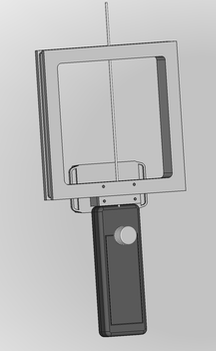
Mechanical Design
The mechanical design is optimized for simplicity, ruggedness, and ergonomic comfort. Left/right symmetry makes the receiver equally usable for left and right handers. Only the front knob (attached to a rotary encoder) extends beyond the walls of the chassis box, helping to minimize the risk of damage during transport or if dropped. Aside from the wires running to the battery, there is no point-to-point wiring - all connections are handled by PCB traces and parts mounted to the circuit board, eliminating unreliable point-to-point wiring. The headphone jack is on the bottom of the receiver, preventing water intrusion. The square antenna geometry makes for a stronger loop that can be readily fabricated using 3D printing. Switches for sense and configuration are recessed and immune to water penetration. The battery can be charged or replaced without opening the receiver chassis. If something breaks or wears out, all parts are readily available from online vendors, and the schematic diagram and BOM are provided, facilitating customer troubleshooting and repair.
Electronics Design
The electronics design is optimized to avoid part obsolescence and to provide high performance. SignalSnagger uses a Software Defined Radio design, utilizing a quadrature sampling detector to provide high dynamic range and to maximize software-upgradable features. A 25-MHz processor capable of sampling the baseband signal can filter and process the audio to achieve reliable signal strength indication and signal detection and supports DSP algorithms to achieve unparalleled SNR performance to detect weak signals deep in the noise.
Free and Open Design
The SignalSnagger project is 100% Open Source. All software and hardware design documents can be downloaded from this GitHub repository.
BOM: https://docs.google.com/spreadsheets/d/1Z3T1SeX6hfT8fjVtJgXu2S2YWHPFD_kywdSzAihOS8g/edit?usp=sharing
Also, check out SignalSnagger's sibling transmitter project: SignalSlinger.
Firmware source lives in
Software/AVR128DA48/SignalSnagger.
Development and release work follows the same core OpenARDF policy used by
SignalSlinger, adapted for SignalSnagger's single AVR128DA48 target:
Start repository work with just --list. Use just check for the complete
local change gate and just release-preflight for deterministic
release-candidate and package verification. just release-package creates the
single-target GitHub deliverables: a standalone AVR128DA48 firmware HEX and a
matching release ZIP with metadata, checksums, and programming guidance. The
Si5351 quadrature strategy is experimentally established and must not be
changed without focused regression tests and representative hardware
measurements.
Firmware and software topics integrate through Development1; KiCad and
receiver-simulation topics integrate separately through Development1-KiCad.
Each collector is promoted to main with its own cumulative pull request. Use
just branch-route-check <collector> before topic work and just collector-preflight <collector> before promotion. main remains linear;
collector pull requests use merge commits so topic and synchronized main
ancestry are preserved. After a promotion, use just collector-sync-check <collector> on each focused synchronization topic before merging it.
Every GitHub release follows the mandatory ordered process in RELEASE_WORKFLOW.md, including a reviewed release commit, clean deterministic packaging, an immutable annotated tag, exact two-asset publication, fresh-download verification, and checked post-tag evidence.
| Qty | Value | Footprint | References |
|---|---|---|---|
| 31 | 100nF | Capacitor_SMD:C_0603_1608Metric | C102, C108, C111, C112, C115, C117, C118, C119, C121, C122, C127, C201, C202, C203, C205, C207 +15 |
| 15 | 10k | Resistor_SMD:R_0603_1608Metric | R103, R105, R120, R122, R206, R207, R212, R213, R214, R215, R303, R308, R311, R907, R931 |
| 13 | 10nF | Capacitor_SMD:C_0603_1608Metric | C105, C106, C107, C110, C204, C214, C217, C218, C219, C220, C223, C319, C906 |
| 7 | 10uF | Capacitor_SMD:C_0603_1608Metric | C113, C213, C224, C225, C226, C312, C910 |
| 7 | 1uF | Capacitor_SMD:C_0603_1608Metric | C125, C126, C215, C216, C314, C321, C908 |
| 6 | Jumper_2_Bridged | Jumper:Jumper_THT-1x02_Bridged_Circular | JP103, JP104, JP105, JP106, JP107, JP202 |
| 5 | MMBT2222A | Package_TO_SOT_SMD:SOT-23 | Q101, Q102, Q103, Q104, Q105 |
| 4 | 10 | Resistor_SMD:R_0603_1608Metric | R108, R109, R322, R911 |
| 4 | 100 | Resistor_SMD:R_0603_1608Metric | R106, R117, R209, R916 |
| 4 | 1N914WT | Diode_SMD:D_SOD-523 | D201, D202, D205, D206 |
| 4 | 1k | Resistor_SMD:R_0603_1608Metric | R102, R121, R204, R313 |
| 4 | 36-5005-ND | Connector_Pin:Pin_D1.6mm_L8.5mm_W2.8mm_FlatFork | J105, J108, J302, J903 |
| 4 | 47uF | Capacitor_SMD:C_1210_3225Metric | C210, C211, C320, C907 |
| 4 | Conn_01x02 | Connector_PinSocket_1.27mm:PinSocket_1x02_P1.27mm_Vertical | J203, J204, J218, J219 |
| 3 | 2.7k | Resistor_SMD:R_0603_1608Metric | R110, R111, R119 |
| 3 | 36-5006-ND | Connector_Pin:Pin_D1.6mm_L8.5mm_W2.8mm_FlatFork | J106, J107, J304 |
| 3 | 470 | Resistor_SMD:R_0603_1608Metric | R107, R321, R910 |
| 3 | 49.9 | Resistor_SMD:R_0603_1608Metric | R112, R118, R914 |
| 3 | 51k | Resistor_SMD:R_0603_1608Metric | R306, R309, R903 |
| 2 | 10 | Resistor_SMD:R_0805_2012Metric | R320, R909 |
| 2 | 100k | Resistor_SMD:R_0603_1608Metric | R101, R201 |
| 2 | 100k | Potentiometer_SMD:Potentiometer_Bourns_TC33X_Vertical | RV302, RV901 |
| 2 | 150nF | Capacitor_SMD:C_0603_1608Metric | C310, C901 |
| 2 | 22uF | Capacitor_SMD:C_0805_2012Metric | C325, C912 |
| 2 | 390pF | Capacitor_SMD:C_0603_1608Metric | C116, C919 |
| 2 | 4.7k | Resistor_SMD:R_0603_1608Metric | R304, R901 |
| 2 | 4.7nF | Capacitor_SMD:C_0603_1608Metric | C311, C902 |
| 2 | 4.99k | Resistor_SMD:R_0603_1608Metric | R113, R915 |
| 2 | 470nF | Capacitor_SMD:C_0603_1608Metric | C206, C208 |
| 2 | 47nF | Capacitor_SMD:C_0603_1608Metric | C114, C918 |
| 2 | 49.9k | Resistor_SMD:R_0603_1608Metric | R310, R930 |
| 2 | 69830-008LF | Connector_Amphenol:69830-008LF | J102, J104 |
| 2 | 7.5k | Resistor_SMD:R_0603_1608Metric | R305, R902 |
| 2 | Conn_01x03 | Connector_PinHeader_1.27mm:PinHeader_1x03_P1.27mm_Vertical | TP301, TP901 |
| 2 | Conn_01x04 | Connector_PinHeader_1.27mm:PinHeader_1x04_P1.27mm_Vertical | J208, J209 |
| 2 | DG9422E | Package_SO:TSOP-6_1.65x3.05mm_P0.95mm | U104, U105 |
| 2 | LM386 | Package_SO:SOIC-8_3.9x4.9mm_P1.27mm | U304, U902 |
| 2 | LP2985-5.0 | Package_TO_SOT_SMD:SOT-23-5 | U203, U206 |
| 2 | SW_SPST | Button_Switch_SMD:SW_SPST_TL1014BF160QG | SW201, SW202 |
| 2 | SolderJumper_2_Open | Jumper:SolderJumper-2_P1.3mm_Open_RoundedPad1.0x1.5mm | JP201, JP301 |
| 2 | TS912IDT | Package_SO:SO-8_3.9x4.9mm_P1.27mm | U302, U901 |
| 1 | +7.4V 2S Battery | Connector_Wire:SolderWire-1sqmm_1x02_P7.8mm_D1.4mm_OD3.9mm_Relief | BT201 |
| 1 | 100pF | Capacitor_SMD:C_0603_1608Metric | C101 |
| 1 | 10k 10T | Potentiometer_THT:Potentiometer_Bourns_3362P_Vertical | RV101 |
| 1 | 10uH | Inductor_SMD:L_0603_1608Metric | L201 |
| 1 | 12.4k | Resistor_SMD:R_0603_1608Metric | R203 |
| 1 | 162k | Resistor_SMD:R_0603_1608Metric | R202 |
| 1 | 220 | Resistor_SMD:R_0603_1608Metric | R205 |
| 1 | 22k | Resistor_SMD:R_0603_1608Metric | R104 |
| 1 | 25 MHz | Crystal:Crystal_SMD_TXETCLSANF-4Pin | X202 |
| 1 | 2pF | Capacitor_SMD:C_0603_1608Metric | C109 |
| 1 | 330k | Resistor_SMD:R_0603_1608Metric | R307 |
| 1 | 35RASMT2BHSNTRX | Connector_Audio:SWITCHCRAFT_35RASMT2BHSNTRX | J301 |
| 1 | 51pF | Capacitor_SMD:C_0603_1608Metric | C104 |
| 1 | 8.5-100pF | Capacitor_THT:VC07B | C103 |
| 1 | AVR128DA48 | Package_QFP:TQFP-48_7x7mm_P0.5mm | U201 |
| 1 | BSS138W-7-F | Package_TO_SOT_SMD:SOT-323_SC-70 | Q202 |
| 1 | Coilcraft_PWB-4-CLC | Inductor_SMD:Coilcraft-PWB-4-CLC | T101 |
| 1 | EA_DOGS104W-A | Display:EA_DOGS104X-A | U205 |
| 1 | ECS-327TXO-30-TR | Oscillator:Oscillator_SMD_ECS_327TXO | X901 |
| 1 | Green LED | LED_SMD:LED_0805_2012Metric | D204 |
| 1 | I2C1 | Connector_PinSocket_1.27mm:PinSocket_1x04_P1.27mm_Vertical | TP201 |
| 1 | ISP/PDI | Connector_PinHeader_2.54mm:PinHeader_2x03_P2.54mm_Vertical | P201 |
| 1 | LP2985-3.3 | Package_TO_SOT_SMD:SOT-23-5 | U204 |
| 1 | MAX1683EUK | Package_TO_SOT_SMD:SOT-23-5 | U207 |
| 1 | MSS1P4-M3 | Diode_SMD:DO-219AD | D301 |
| 1 | NTS4173PT1G | Package_TO_SOT_SMD:SOT-323_SC-70 | Q201 |
| 1 | PEC12R-4225F-S0024 | Rotary_Encoder:RotaryEncoder_Bourns_PEC12R-Switch_Vertical_CircularMountingHoles | SW203 |
| 1 | QS3253QG8 | Package_SO:SSOP-16_4.4x5.2mm_P0.65mm | U102 |
| 1 | REF4132B33 | Package_TO_SOT_SMD:SOT-23-5 | U103 |
| 1 | Red LED | LED_SMD:LED_0805_2012Metric | D203 |
| 1 | SI5351 | Package_SO:MSOP-10_3x3mm_P0.5mm | U202 |
| 1 | np | Connector_PinHeader_1.27mm:PinHeader_1x03_P1.27mm_Vertical | RV102 |
The 203 most common of 207 parts.
It measures 133.4 × 44.3 mm and has 4 copper layers, 1.61 mm thick.
207 parts, built around the AVR128DA48, LM386, TS912IDT and LP2985-50DBV. The full list of its parts is on this page, with links to each part's symbol and footprint where PCBKit's library has them.
From the OpenARDF/SignalSnagger repository on GitHub, at the commit this page was made from: the board is KiCad/SignalSnagger/SignalSnagger.kicad_pcb and its schematic KiCad/SignalSnagger/SignalSnagger.kicad_sch. PCBKit opens the board in the browser, with nothing to install.
Its repository publishes it under the MIT licence: you may reuse it on that licence's terms (keep the author's notice, and for a copyleft licence share your changes alike).

fiskebolle30/Bachelor_Electronics_hardware
All PCB design files for the bachelor project. Project is made in KiCad


fotherja/Grid_Tie_Inverter_V5
Please refer to my site ( www.jamesfotherby.com ) where this project is being documented in detail


thomasfla/ARDUINO_PICO_TMC2130
Control 3 TMC2130 stepper driver via USB comands (TMX2130 + RP2350 / RP2040)