2 layers97.8 × 71.1 mm
Basic Clock
oli4wolf/Split-Flap-Display
Documentation for the Split-Flap-Display project with the apprentice
38 partsGPL-3.0
 oli4wolf/Split-Flap-Display
Documentation for the Split-Flap-Display project with the apprentice
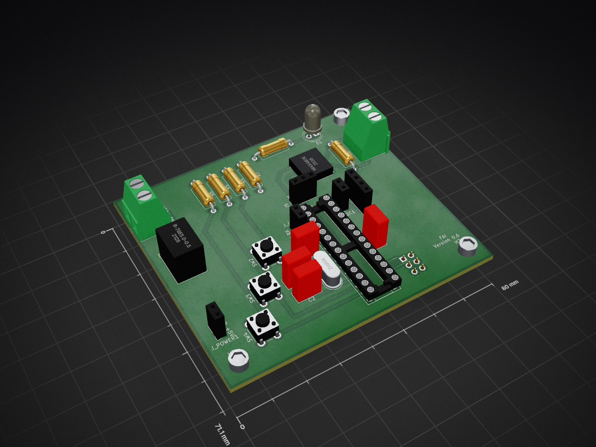
Basic Clock is an open-source printed circuit board by oli4wolf, from the oli4wolf/Split-Flap-Display repository on GitHub, published under the GPL-3.0 licence. It is a 2-layer board of 80 × 71.1 mm with 30 parts on 22 nets, routed with 90 tracks and 2 vias.
It is built around the ATMEGA328P-PU, MAX485ED and R-78E5.0-0.5. Its parts include 6 resistors, 4 capacitors, 4 connectors, 3 ICs and 3 switches. It belongs with the lEDs and displays boards and the AVR (ATmega, ATtiny) boards of this library.


Version 1.1 Changes
| Qty | Value | Footprint | References |
|---|---|---|---|
| 4 | 10k | Resistor:R_Axial_DIN0309_L9.0mm_D3.2mm_P12.70mm_Horizontal | R4, R5, R6, R7 |
| 4 | MountingHole | MountingHole:MountingHole_3.2mm_M3_ISO14580 | H1, H2, H3, H4 |
| 3 | Conn_01x02_Female | Connector THT:PinSocket_1x02_P2.54mm_Vertical | J_I2C1, J_I2C2, J_POWER1 |
| 3 | SW_Push | Button THT:SW_PUSH_6mm_H5mm | SW2, SW3, SW4 |
| 2 | 100nF | Capacitor_THT:C_Rect_L7.0mm_W3.5mm_P5.00mm | C6, C7 |
| 2 | 22pf | Capacitor THT:C_Rect_L7.0mm_W3.5mm_P5.00mm | C1, C2 |
| 2 | Screw_Terminal_01x02 | TerminalBlock_RND:TerminalBlock_RND_205-00232_1x02_P5.08mm_Horizontal | J3, J4 |
| 1 | 120 | Resistor:R_Axial_DIN0309_L9.0mm_D3.2mm_P12.70mm_Horizontal | R8 |
| 1 | 16Mhz | Quartz:Crystal_HC49-4H_Vertical | Y1 |
| 1 | 1K | Resistor:R_Axial_DIN0309_L9.0mm_D3.2mm_P12.70mm_Horizontal | R3 |
| 1 | ATmega328P-PU | Package_DIP:DIP-28_W7.62mm_Socket | U2 |
| 1 | Conn_01x03_Female | Connector THT:PinSocket_1x03_P2.54mm_Vertical | J5 |
| 1 | Conn_01x04_Female | Connector THT:PinSocket_1x04_P2.54mm_Vertical | J1 |
| 1 | Conn_02x03_Odd_Even | Connector_PinSocket_2.54mm:PinSocket_2x03_P2.54mm_Vertical | ICSP1 |
| 1 | MAX485E | MAX485:DIP794W47P254L991H457Q8 | U3 |
| 1 | Power LED | LED:LED_D5.0mm_Clear | D1 |
| 1 | R-78E5.0-0.5 | Converter_DCDC:Converter_DCDC_RECOM_R-78E-0.5_THT | U4 |
It measures 80 × 71.1 mm and has 2 copper layers, 1.6 mm thick.
30 parts, built around the ATMEGA328P-PU, MAX485ED and R-78E5.0-0.5. The full list of its parts is on this page, with links to each part's symbol and footprint where PCBKit's library has them.
From the oli4wolf/Split-Flap-Display repository on GitHub, at the commit this page was made from: the board is PCBs/Basic_Clock_v0.6/Basic_Clock.kicad_pcb. PCBKit opens the board in the browser, with nothing to install.
Its repository publishes it under the GPL-3.0 licence: you may reuse it on that licence's terms (keep the author's notice, and for a copyleft licence share your changes alike).
oli4wolf/Split-Flap-Display
Documentation for the Split-Flap-Display project with the apprentice

oli4wolf/Split-Flap-Display
Documentation for the Split-Flap-Display project with the apprentice

oli4wolf/Split-Flap-Display
Documentation for the Split-Flap-Display project with the apprentice

oli4wolf/Split-Flap-Display
Documentation for the Split-Flap-Display project with the apprentice

antoinem01/torqeedo_motor
Arduino sketch to control a Torqeedo electric outboard motor over RS485, with speed control and safety switches

sitlesh/IoT-Enabled-Smart-RS-485-Modbus-Sensor-Node
Industrial-grade Modbus RTU communication node featuring full galvanic isolation between the ATmega328P logic block and the RS485 network. Designed in KiCad with an optimized on-board LM2596 switching buck regulator.

ohmtech-rdi/eurorack-blocks
Software to Hardware Prototyping for Eurorack using C++, Max/Gen~ or Faust

cvonk/OPNpool
Integrates the functionality of a Pentair pool controller into the smart home using ESP32 SoC.

Edging-Machines/Edging-Machines
This repository is intended to contain as much information as possible about building, designing, prototyping, and using automated edging machines.


emeb/up5k_osc
The brute-force approach is to synthesize these analog waveforms at sufficiently high sample rates that the timing jitter becomes imperceptible.