4 layers68.6 × 53.3 mm
Boysenboard
MillerTechnologyPeru/boysenboard
Linux capable single board computer using the F1C200s in an Arduino form-factor.
97 parts2GPL-3.0
 o7-machinehum/RTShield13
Breakout board for a RPi.
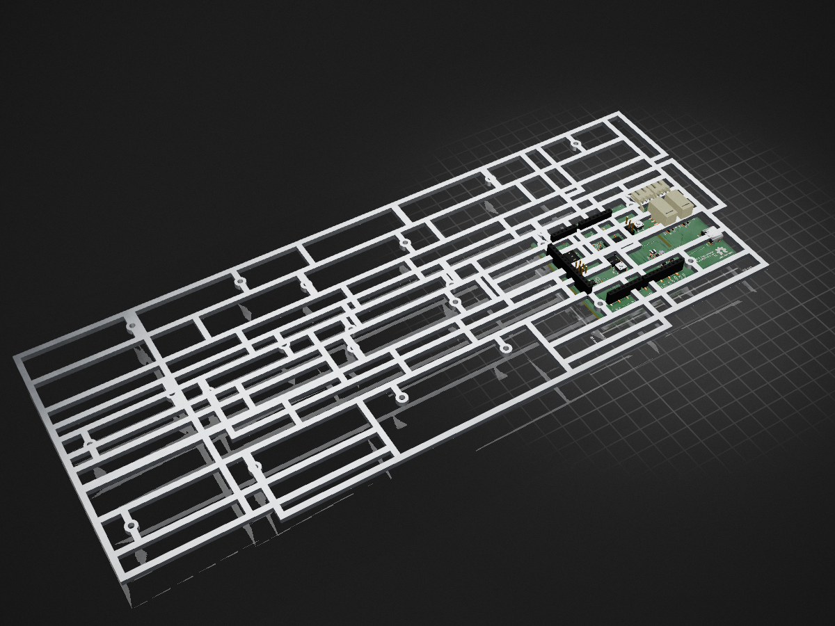
Blocky breakout pcb is an open-source printed circuit board by o7-machinehum, from the o7-machinehum/RTShield repository on GitHub. It is a 4-layer board of 89 × 61 mm with 95 parts on 144 nets, routed with 787 tracks and 133 vias.
It is built around the RP2350B, AOZ1280CI and MCP4728-E/UN, with the W25Q32JVSSIQ, LM66100DCK and LM4040C33FTA among its other parts. Its parts include 30 capacitors, 22 resistors, 11 connectors, 9 ICs and 6 diodes. It belongs with the interfaces and adapters boards and the RP2350 boards of this library.


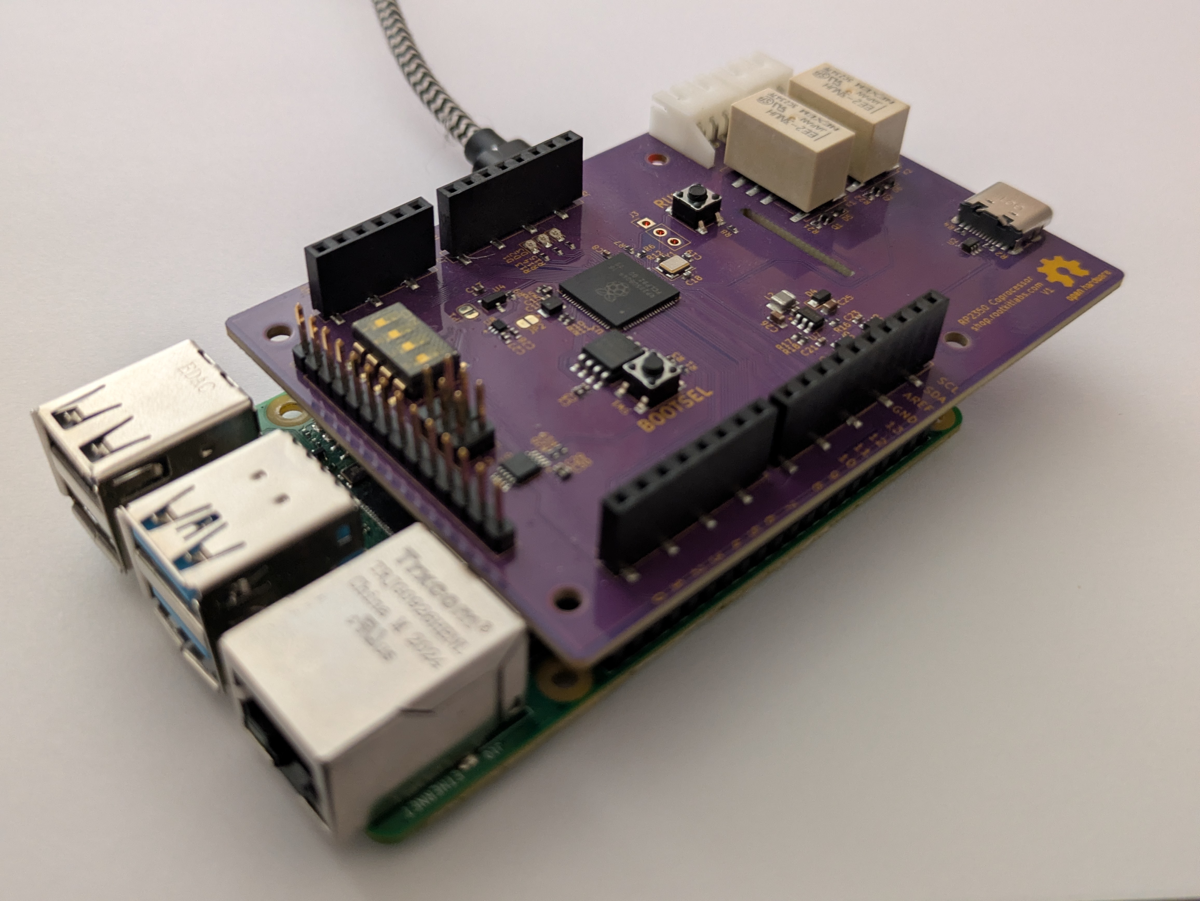 The RTSheild is a Raspberry PI hat containing an MCU to serve as a "realtime" companion. The PI is connected to the RP2350 over a UART link, and all sensors are wired into the RP2350 itself. The RP2350 is connected to Arduino compatible headers
git clone https://github.com/o7-machinehum/RTShield
cd RTShield
git submodule update --init --recursive

sudo apt update
sudo apt install -y build-essential cmake ninja-build gcc-arm-none-eabi \
    libnewlib-arm-none-eabi python3-dev python3-pybind11 openocd

sudo raspi-config nonint do_serial_cons 1
sudo raspi-config nonint do_serial_hw 0
sudo usermod -aG dialout "$USER"

make
make flash # This flashes the RP2350

make install

# Reboot once so the serial-console setting and dialout group membership apply.
sudo rebootThe Python API talks to the shield over /dev/serial0:
import rtshield

s = rtshield.Shield("/dev/serial0")
print(s.read_analog_raw(0))
s.write_analog_voltage(0, 1.25)
s.write_digital(2, True)
s.set_led(0, True)
s.set_relay(0, True)
print(s.read_switch(0))It's worth mentioning the UART between the MCU and the RPI isn't done very nicely right now. This is to keep things simple. I will eventually do a proper cobs encoding scheme and make things nicer.
The project is licensed under the Creative Commons (4.0 International License) Attribution—Noncommercial—Share Alike license. This allows sharing and adapting material for non-commercial purposes, provided credit is given to the creator and adaptations are shared under the same terms. The material can be used in any format with necessary technical modifications, but no warranties are provided. The license prohibits imposing additional restrictions and ensures the rights are irrevocable as long as the terms are followed.
Basically... If you make boards for yourself: great, make boards for your friends: great, but please do not sell hundreds on them on Aliexpress.
Files in docs/ 3rd party reference material are not covered by this licence.
| Qty | Value | Footprint | References |
|---|---|---|---|
| 16 | 100nF | Capacitor_SMD:C_0402_1005Metric | C2, C3, C4, C5, C7, C8, C9, C10, C11, C12, C13, C20, C21, C22, C23, C29 |
| 12 | 1k | Resistor_SMD:R_0402_1005Metric | R3, R6, R8, R9, R12, R13, R14, R15, R19, R20, R21, R22 |
| 6 | 4.7uF | Capacitor_SMD:C_0402_1005Metric | C6, C14, C15, C16, C17, C30 |
| 4 | 1uF | Capacitor_SMD:C_0402_1005Metric | C1, C24, C27, C28 |
| 4 | 2.7mm | MountingHole:MountingHole_2.7mm_M2.5 | H1, H2, H3, H4 |
| 3 | 27R | Resistor_SMD:R_0402_1005Metric | R5, R10, R11 |
| 2 | 10uF | Capacitor_SMD:C_0603_1608Metric | C25, C26 |
| 2 | 15pF | Capacitor_SMD:C_0402_1005Metric | C18, C19 |
| 2 | 5.6k | Resistor_SMD:R_0402_1005Metric | R2, R4 |
| 2 | BAT54XV2T1G | Diode_SMD:D_SOD-523 | D5, D6 |
| 2 | Conn_01x03_Pin | Connector_JST:JST_XH_S3B-XH-A-1_1x03_P2.50mm_Horizontal | J10, J11 |
| 2 | Conn_01x08_Pin | Connector_PinSocket_2.54mm:PinSocket_1x08_P2.54mm_Vertical_SMD_Pin1Left | J5, J8 |
| 2 | DMG1012TQ-7 | Package_TO_SOT_SMD:SOT-523 | Q1, Q2 |
| 2 | EE2-3TNUH | Relay_SMD:Relay_DPDT_Kemet_EE2_NU | K1, K2 |
| 2 | LM66100DCK | Package_TO_SOT_SMD:SOT-363_SC-70-6 | U5, U6 |
| 2 | SW_Push | Button_Switch_SMD:SW_SPST_PTS647_Sx38 | SW1, SW2 |
| 2 | SolderJumper_2_Open | Jumper:SolderJumper-2_P1.3mm_Open_RoundedPad1.0x1.5mm | JP1, JP2 |
| 1 | 0R | Resistor_SMD:R_0402_1005Metric | R7 |
| 1 | 100k | Resistor_SMD:R_0402_1005Metric | R16 |
| 1 | 10k | Resistor_SMD:R_0402_1005Metric | R1 |
| 1 | 12Mhz | X_Abracon:Crystal_SMD_Abracon_ABM8-272-T3-4Pin_3.2x2.5mm | Y1 |
| 1 | 15.8k | Resistor_SMD:R_0402_1005Metric | R18 |
| 1 | 2.2uH | Inductor_SMD:L_1008_2520Metric | L2 |
| 1 | 3u3 | L_Abracon:AOTA-B201610S3R3-101-T | L1 |
| 1 | 49.9k | Resistor_SMD:R_0402_1005Metric | R17 |
| 1 | AOZ1280CI | Package_TO_SOT_SMD:SOT-23-6 | U7 |
| 1 | Conn_01x03_Pin | Connector_PinHeader_2.54mm:PinHeader_1x03_P2.54mm_Vertical | J3 |
| 1 | Conn_01x06_Pin | Connector_PinSocket_2.54mm:PinSocket_1x06_P2.54mm_Vertical_SMD_Pin1Left | J7 |
| 1 | Conn_01x10_Pin | Connector_PinSocket_2.54mm:PinSocket_1x10_P2.54mm_Vertical_SMD_Pin1Left | J6 |
| 1 | Conn_01x14_Pin | Connector_PinHeader_2.54mm:PinHeader_1x14_P2.54mm_Vertical | J2 |
| 1 | Conn_02x03_Odd_Even | Connector_PinHeader_2.54mm:PinHeader_2x03_P2.54mm_Vertical | J9 |
| 1 | Green | LED_SMD:LED_0603_1608Metric | D2 |
| 1 | LM4040C33FTA | Package_TO_SOT_SMD:SOT-23 | U4 |
| 1 | MCP4728 | Package_SO:MSOP-10_3x3mm_P0.5mm | U9 |
| 1 | MSS2P3 | Diode_SMD:D_MicroSMP_AK | D4 |
| 1 | NUP2202 | Package_TO_SOT_SMD:SOT-363_SC-70-6 | U2 |
| 1 | RP2350 | Package_DFN_QFN:QFN-80-1EP_10x10mm_P0.4mm_EP3.4x3.4mm | U3 |
| 1 | Raspberry_Pi_4 | Connector_PinSocket_2.54mm:PinSocket_2x20_P2.54mm_Vertical_SMD | J4 |
| 1 | Red | LED_SMD:LED_0603_1608Metric | D1 |
| 1 | SW_DIP_x04 | Button_Switch_SMD:SW_DIP_SPSTx04_Slide_Omron_A6S-410x_W8.9mm_P2.54mm | SW3 |
| 1 | TCR2EE11 | Package_TO_SOT_SMD:SOT-553 | U8 |
| 1 | USB_C_Receptacle_USB2.0_16P | Connector_USB:USB_C_Receptacle_GCT_USB4105-xx-A_16P_TopMnt_Horizontal | J1 |
| 1 | W25Q32JVSS | Package_SO:SOIC-8_5.3x5.3mm_P1.27mm | U1 |
| 1 | Yellow | LED_SMD:LED_0603_1608Metric | D3 |
The 94 most common of 95 parts.
It measures 89 × 61 mm and has 4 copper layers, 1.6 mm thick.
95 parts, built around the RP2350B, AOZ1280CI, MCP4728-E/UN and W25Q32JVSSIQ. The full list of its parts is on this page, with links to each part's symbol and footprint where PCBKit's library has them.
From the o7-machinehum/RTShield repository on GitHub, at the commit this page was made from: the board is pcb/blocky_breakout_pcb.kicad_pcb and its schematic pcb/arduino_headers.kicad_sch. PCBKit opens the board in the browser, with nothing to install.
Its repository states no licence, so its author keeps all rights: ask o7-machinehum before reusing the design.
MillerTechnologyPeru/boysenboard
Linux capable single board computer using the F1C200s in an Arduino form-factor.

o7-machinehum/Blackpants
Open blackpants.kicadpro for the active A523 schematic and PCB. It replaces the A33 hierarchy and uses AXP717C + AXP323 with 2GB LPDDR4.

filliformes/pandore
pandore is an open-source digital audio instrument protyping platform based on the LattePanda Mu.


JackoChan2005/TTC-Map
A Toronto rail explorer and ESP32 LED display built around one transit-state API. The web map shows Lines 1, 2, 4, 5 and 6 over OpenStreetMap, with route search, station details, directional markers and a schematic view.

PUT-Motorsport/PUTM_EV_FRONTBOX
PCB board aquiring data from the front side of the vehicle

PUT-Motorsport/PUTM_EV_REARBOX
A PCB combining components for the rear side of the vehicle

matthieuvigne/MiAM_robotics
Generic repo for robotic projects with the former MiAM Eurobot team !