4 layers89 × 61 mm

 filliformes/pandore2
pandore is an open-source digital audio instrument protyping platform based on the LattePanda Mu.
Pandore is an open-source printed circuit board by filliformes, from the filliformes/pandore repository on GitHub. It is a 4-layer board of 260 × 110 mm with 804 parts on 833 nets, routed with 8,837 tracks and 2,217 vias.
It is built around the OPA1656ID, AP63356QZV and LDL212DR, with the 0402B104K160CT, CR0402-FX-1002GLF and RC0402JR-070RL among its other parts. Its parts include 288 capacitors, 277 resistors, 40 diodes, 21 ICs and 15 transistors. It belongs with the audio and music boards of this library.


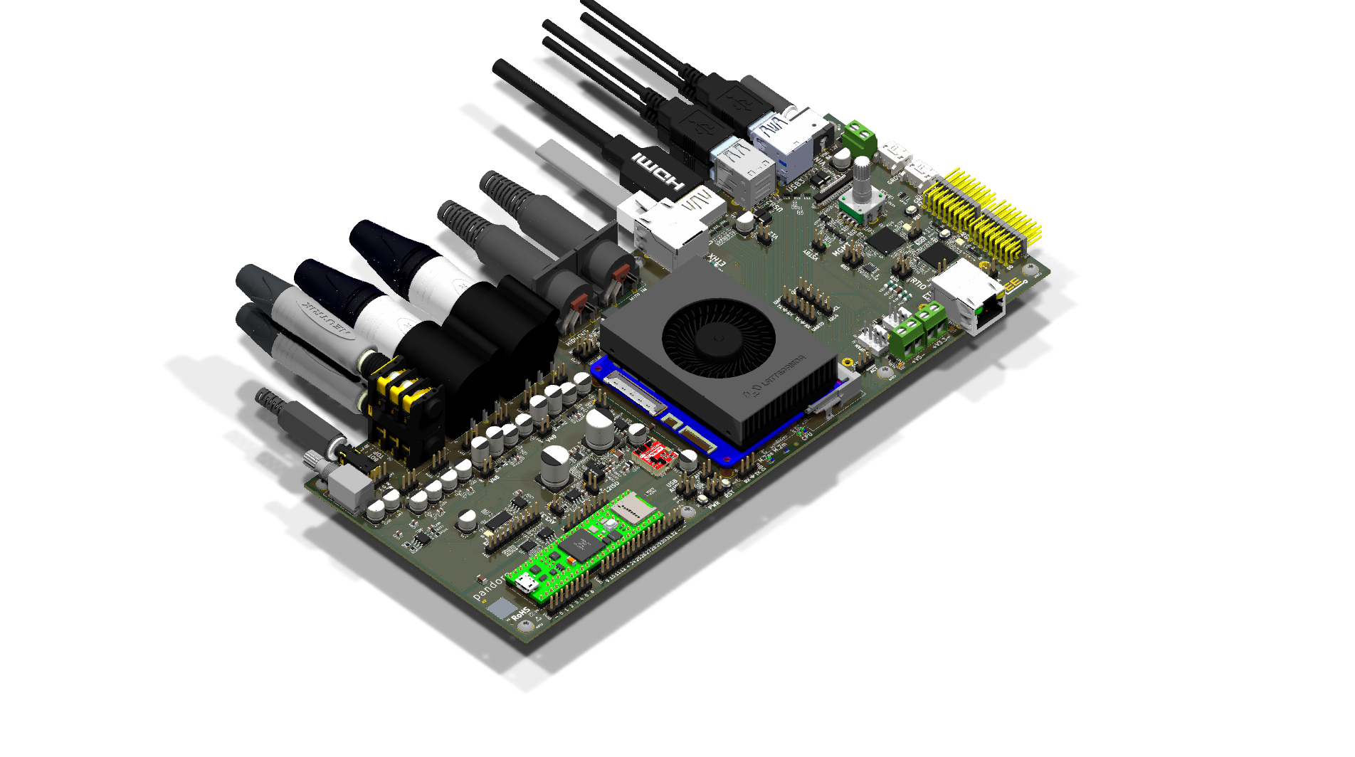
Open-source digital audio instrument prototyping platform.
Pandore is a custom-designed PCB built around the LattePanda Mu compute module, a Teensy 4.1 audio bridge, dual RP2350 microcontrollers, and a professional audio I/O chain. It provides a complete hardware foundation for building digital audio instruments, effects processors, and experimental sound tools.
Revision A0 — PCBA complete at PCBWay (3 units); hand-assembly of the through-hole/DNP parts and board bring-up in progress. Manufacturing files released 2026-03-19; DRC passing. See the interactive BOM and the A0 bring-up / hand-assembly guide.
PCBWay substitution: RP2350A was unavailable at assembly time; PCBWay substituted RP2350B (QFN-80) for both MCU positions. RP2350A and RP2350B are binary-compatible — same cores, same peripherals, same memory map — they differ only in package size and number of exposed GPIO pins (30 vs 48). Firmware developed on RP2350A Pico boards transfers without modification.
| Parameter | Value |
|---|---|
| Dimensions | 260 mm x 110 mm |
| Layers | 4 (F.Cu / In1 / In2 / B.Cu) |
| Components | 804 (141 unique part numbers) |
| Vias | 2,217 |
| Design tool | KiCad 10 |
                         +-----------------+
                         |  LattePanda Mu  |
                         |  (x86-64 SBC)   |
                         +--------+--------+
                                  |
          +----------+-----------+-----------+----------+
          |          |                       |          |
 +--------+-------+  |             +---------+--------+ |
 |  RTIO MCU      |  |             |  Management MCU  | |
 |  (RP2350)      |  |             |  (RP2350)        | |
 +--------+-------+  |             +---------+--------+ |
          |          |                       |          |
 +--------+-------+  |             +---------+--------+ |
 | UART, SPI, I2C |  |             | GPIO, Power Seq, | |
 | ADC, 8x PWM    |  |             | Fan, Display     | |
 +----------------+  |             +------------------+ |
                     |                                  |
            +--------+--------+                         |
            |   Teensy 4.1    |                         |
            | (I2S-to-USB     |                         |
            |  Audio Bridge)  |                         |
            +--------+--------+                         |
                     |                                  |
+--------+--------+ +---------+--------+| Rail | Voltage | Current | Purpose |
|---|---|---|---|
| 12V | Main input | LattePanda Mu, OLED drive | |
| 5V | 2A (10W) | Digital logic, USB peripherals | |
| 3.3V | 3A (10W) | MCUs, codec digital, I/O | |
| 48V | 10 mA | Condenser microphone phantom power | |
| AV5 / AV3P3 | — | Analog audio supply (isolated domain) | |
| VSTBY | ~3.3V | Standby (CR2032 backup) |
Power ICs:
| Part | Role |
|---|---|
| Diodes AP63356Q (×2) | Synchronous buck converters (3.5A), main DC-DC regulation |
| STM LDL212DR (×3) | Ultra-low-dropout LDOs, local clean rails |
| ETEK ET20162 (×5) | USB VBUS current-limit load switches, 1A fixed each (U29–U32 = 4 USB-A ports, U33 = Teensy USB host) |
| TI LM5158RTER | Flyback controller for 48V phantom supply |
| TI TPS7A4001DGNR | Ultra-low-noise 40V LDO, phantom post-regulation |
| Murata NXE2S1212MC-R7 | 2W isolated 12V DC/DC (167 mA) for audio analog domain |
The two Grove connectors (J17/J18) are I2C sensor ports running at 3.3V — each on its own management-MCU I2C bus (J17 = I2C0, J18 = I2C1), powered from the standby rail through a 0.1A PTC fuse.
Because the ports are 3.3V, use the Qwiic / STEMMA QT sensor ecosystem (SparkFun, Adafruit, Arduino Modulino) — it is 3.3V-native, so modules plug in safely with no level shifting. A standard Grove-to-Qwiic adapter cable (Adafruit #4528 or SparkFun PRT-15109) connects them. Note: M5Stack Units are powered at 5V and are not directly compatible.
3× Winbond W25Q128JVSIM (128 Mbit / 16 MB, QSPI):
See Audio Performance for the full signal chain, component specs, system-level estimates, physical I/O, and performance class.
Highlights: 24-bit / 192 kHz, 114 dB dynamic range, -100 dB THD+N, 5000 VRMS galvanic isolation, 2× Neutrik combo XLR+TRS inputs with 48V phantom power.
pandore/
  hw/               Schematics (.kicad_sch) and PCB layout (.kicad_pcb)
  doc/
    arch/           Architecture diagrams (draw.io)
    img/            Board renders
    reference/      Datasheets, app notes, design guides (PDF)
  lib/              3D models (.step), KiCad symbols and footprints
release/ Manufacturing artifacts (Gerbers, BOM, placement, 3D)The top-level schematic (pandore.kicad_sch) references 24 sub-sheets organized by subsystem:
Audio — audio, audio-codec, audio-inputs, audio-inbuf, audio-outputs, audio-outbuf, audio-isolation, audio-monitor, audio-power
Compute — computer, cpumod, mcu, mgmtmcu, rtmcu
Power — power, audio-power
Interface — eth, usbport, midi, display, extraport, mdot2
System — bootctl, bios, fan
The PCBWay PCBA order covers all SMD components. The following through-hole and DNP parts must be sourced and hand-soldered separately. BOM part numbers are listed; substitutions are noted where a different part is recommended over the original BOM.
| BOM# | Per board | Ref | Description | Part (installed) | Notes |
|---|---|---|---|---|---|
| 40 | 1 | E1 | Encoder + RGB LED + switch | Bourns PEL12T-4225T-S1024 | 24 PPR, push switch, RGB illuminated |
| 47 | 2 | J4, J5 | Mic/Line input combo jack | Neutrik NCJ9FI-H-0 | XLR + 6.35mm TRS + 3-way switch |
| 50 | 2 | J8, J9 | Ethernet RJ45 | Amphenol RJE58-188-5441 | 8P8C shielded, dual LEDs, Cat5e (replaces BOM -5411, backordered; same footprint) |
| 51 | 2 | J10, J11 | MIDI DIN | Same Sky SDS-50J | 5-pin DIN 180° |
| 52 | 1 | J12 | Line output TRS | Neutrik NSJ12HF-1 | 6.35mm stacking stereo |
| 55 | 2 | J15, J16 | GPIO expansion header | Samtec MTSW-108-22-L-T-330-RA | 3×8 right-angle, 2.54mm pitch |
| 56 | 2 | J17, J18 | Grove connectors | TE 440055-4 | HPI 2.0mm R/A THT (replaces BOM 2041145-4, same family) |
| 105 | 1 | R273 | Headphone volume pot | Bourns PTR902-2020K-A103 | Audio taper, 20mm shaft (replaces BOM 2015K-B103, linear, 15mm) |
| — | 1 | J25 | OLED display panel | Microtips REX012864AYAP3N00000 (primary) or Midas MCOT128064B1V-WM (alt) | SSD1309, 128×64, 24-pin 0.5mm FPC; J25 ZIF socket is PCBWay-assembled |
| — | 1 | U9 | Audio/MIDI bridge module | PJRC Teensy 4.1 (SparkFun DEV-20359, headerless) | Mounted on Samtec TSW headers; its own USB-C jack is exposed at the panel |
| — | 2 | J28, J29 | Teensy USB-D± pogo pins | Same Sky CPG-23-SMT-TR | Spring contacts tapping the Teensy's underside USB-D+/D− pads — not USB-C receptacles; hand-soldered |
| — | 1 | J13 | NVMe SSD | User choice | M.2 2280 Key-M, PCIe x4 |
| — | 1 | J19 | WiFi/BT module | Intel AX210 (WiFi 6E + BT 5.3) | M.2 2230 Key-E |
The release/ directory contains two packages dated 2026-03-19 (revision A0):
pandore_*_A0_pcba.zip — PCBA package: Gerbers, drill files, BOM (.csv), pick-and-place (.pos)pandore_*_A0_release.zip — Full release: PCBA files + 3D assembly model (.step), assembly drawings (PDF), rendered board images, ERC/DRC reports4-layer stackup. 2,439 drill holes. All components have manufacturer part numbers assigned.
The doc/reference/ directory includes datasheets and design guides used during development:
Designed by Vincent Fillion at Artificiel, with the help of Alexandre Burton.
Hardware engineering and KiCad source files by Laurence Deschênes Villeneuve (@laurencedv).
This project is licensed under the CERN Open Hardware Licence Version 2 — Strongly Reciprocal (CERN-OHL-S-2.0).
You are free to use, study, modify, and distribute this design, provided that:
| Qty | Value | Footprint | References |
|---|---|---|---|
| 109 | 100nF, 25V, X7R | reekilib_cap:CAPC1005 | C10, C11, C12, C13, C14, C15, C16, C17, C113, C114, C115, C116, C119, C133, C140, C156 +93 |
| 57 | 10kΩ, 1%, 63mW | reekilib_res:RESC1005 | R10, R13, R17, R106, R107, R108, R109, R129, R130, R133, R134, R140, R141, R143, R144, R155 +41 |
| 34 | 10µF, 25V, X5R | reekilib_cap:CAPC2012 | C100, C101, C102, C111, C112, C120, C134, C155, C157, C186, C188, C196, C197, C198, C230, C231 +18 |
| 28 | 0Ω, 5%, 63mW | reekilib_res:RESC1005 | R2, R194, R195, R199, R202, R203, R212, R213, R214, R236, R237, R238, R239, R245, R278, R279 +12 |
| 24 | 1kΩ, 1%, 63mW | reekilib_res:RESC1005 | R14, R15, R16, R21, R22, R23, R132, R139, R177, R207, R218, R220, R229, R230, R234, R235 +8 |
| 22 | 5.1kΩ, 0.5%, thin film | reekilib_res:RESC2012 | R74, R75, R76, R77, R78, R79, R252, R253, R258, R259, R262, R263, R264, R266, R267, R269 +6 |
| 17 | 2.2kΩ, 1%, 63mW | reekilib_res:RESC1005 | R57, R58, R59, R60, R61, R164, R165, R166, R167, R172, R173, R174, R175, R176, R178, R179 +1 |
| 16 | 100pF, 50V, C0G | reekilib_cap:CAPC1608 | C139, C144, C145, C146, C147, C151, C152, C158, C167, C168, C169, C170, C171, C172, C173, C174 |
| 16 | 4.7µF, 6.3V, X5R | reekilib_cap:CAPC1005 | C31, C32, C63, C64, C65, C66, C98, C103, C214, C215, C216, C217, C218, C219, C229, C261 |
| 15 | MOSFET_EN-N | reekilib_sot:SOT95P280X100-3 | Q1, Q2, Q3, Q4, Q5, Q6, Q7, Q8, Q9, Q10, Q11, Q12, Q13, Q14, Q15 |
| 14 | 1µF, 16V, X7R | reekilib_cap:CAPC1608 | C201, C237, C238, C239, C263, C264, C265, C266, C267, C268, C269, C270, C271, C272 |
| 14 | 220nF, 16V, X7R | reekilib_cap:CAPC1005 | C121, C130, C141, C148, C248, C249, C250, C251, C252, C253, C254, C255, C256, C257 |
| 12 | 100µF, 25V, 20% | reekilib_cap:CAPAE630Xxxx | C122, C127, C137, C138, C159, C160, C161, C162, C187, C273, C289, C290 |
| 12 | 1kΩ, 0.5%, thin film | reekilib_res:RESC2012 | R94, R95, R96, R97, R100, R101, R102, R103, R118, R119, R120, R121 |
| 12 | 5V | reekilib_dfn:DFN50P100X250X55-10_ESD204 | D6, D7, D8, D9, D10, D11, D12, D13, D14, D15, D16, D27 |
| 11 | 100pF, 1kV, X5R | reekilib_cap:CAPC3216 | C85, C86, C105, C106, C107, C108, C109, C210, C211, C212, C213 |
| 11 | 10Ω, 1%, thin film | reekilib_res:RESC2012 | R52, R82, R83, R88, R89, R204, R205, R265, R268, R271, R272 |
| 10 | 0Ω, 5%, thin film | reekilib_res:RESC2012 | R131, R138, R142, R147, R227, R260, R261, R270, R274, R275 |
| 10 | 49.9Ω, 1%, 63mW | reekilib_res:RESC1005 | R159, R160, R161, R162, R163, R201, R209, R210, R240, R250 |
| 8 | 1.3nF, 16V, C0G | reekilib_cap:CAPC1608 | C117, C118, C128, C129, C142, C143, C149, C150 |
| 8 | 300pF, 16V, C0G | reekilib_cap:CAPC1608 | C123, C124, C131, C132, C281, C282, C287, C288 |
| 8 | 75Ω, 1%, 250mW | reekilib_res:RESMELF0204 | R34, R35, R36, R37, R38, R39, R40, R41 |
| 7 | 560Ω, 5%, 63mW | reekilib_res:RESCAXSR50P200X100X35-8 | R44, R45, R46, R47, R55, R56, R197 |
| 7 | Mounting | reekilib_mnt:mnt_M3 | MNT2, MNT3, MNT4, MNT5, MNT6, MNT7, MNT8 |
| 7 | orange | reekilib_led:LEDM1608X80 | D23, D24, D26, D29, D30, D31, D33 |
| 6 | 100kΩ, 1%, 63mW | reekilib_res:RESC1005 | R135, R145, R152, R211, R221, R285 |
| 6 | 12pF, 6.3V, X7R | reekilib_cap:CAPC1005 | C73, C74, C75, C76, C96, C97 |
| 6 | 22µF, 25V, X5R | reekilib_cap:CAPC3216 | C180, C181, C182, C192, C193, C194 |
| 6 | 75V, 150mA, 1V@100mA | reekilib_sod:sod-123 | D17, D28, D32, D36, D37, D42 |
| 5 | 2.49kΩ, 1%, 63mW | reekilib_res:RESC1005 | R26, R27, R146, R156, R208 |
| 5 | 5.5V 1A | reekilib_sot:SOT95P280X100-5 | U29, U30, U31, U32, U33 |
| 5 | 560Ω, 1%, 63mW | reekilib_res:RESC1005 | R185, R186, R187, R206, R228 |
| 5 | M2 | reekilib_mnt:mnt_M2_ele | M2AE30, M2M42, M2M60, M2M80, M2M110 |
| 4 | 0Ω, 5%, 63mW | reekilib_res:RESCAXSR50P200X100X35-8 | R168, R169, R170, R171 |
| 4 | 100Ω, 1%, thin film | reekilib_res:RESC2012 | R80, R81, R92, R93 |
| 4 | 10kΩ, 0.5%, thin film | reekilib_res:RESC2012 | R254, R255, R256, R257 |
| 4 | 15pF, 6.3V, X7R | reekilib_cap:CAPC1005 | C37, C38, C39, C40 |
| 4 | 33nF, 16V, X7R | reekilib_cap:CAPC1608 | C125, C126, C135, C136 |
| 4 | 33µF, 63V, 20% | reekilib_cap:CAPAE630Xxxx | C163, C164, C165, C166 |
| 4 | 40.2Ω, 0.5%, thin film | reekilib_res:RESC2012 | R98, R99, R104, R105 |
| 4 | 470Ω, 1%, 63mW | reekilib_res:RESC1005 | R28, R29, R30, R31 |
| 4 | 47kΩ, 0.5%, thin film | reekilib_res:RESC2012 | R114, R115, R116, R117 |
| 4 | 6.8kΩ, 0.5%, thin film | reekilib_res:RESC2012 | R122, R123, R124, R125 |
| 4 | 6V | reekilib_dio:dio_sma | D38, D39, D40, D41 |
| 4 | 75V, 140mA, 1.25V@150mA | reekilib_sot:SOT65P210X90-3 | D19, D20, D21, D22 |
| 4 | 9.1kΩ, 0.5%, thin film | reekilib_res:RESC2012 | R110, R111, R112, R113 |
| 4 | OPA1656 | reekilib_soic:SOIC127P600X150-8 | U26, U34, U35, U36 |
| 4 | OPAMP_DIFF_1 | reekilib_sop:SOP65P490X300-8 | U15, U16, U17, U18 |
| 4 | green | reekilib_led:LEDM1608X80 | D3, D4, D5, D35 |
| 4 | mom_tact_no | reekilib_msw:tact_460X320X250 | B1, B2, B3, B4 |
| 3 | 100nF, 100V, X7R | reekilib_cap:CAPC2012 | C205, C209, C224 |
| 3 | 10nF, 100V, X7R | reekilib_cap:CAPC1608 | C199, C225, C226 |
| 3 | 10µH | reekilib_ind:INDC2520 | L1, L2, L3 |
| 3 | 1MΩ, 1%, 63mW | reekilib_res:RESC1005 | R24, R25, R222 |
| 3 | 1nF, 16V, X7R | reekilib_cap:CAPC1005 | C183, C190, C204 |
| 3 | 21kΩ, 1%, 63mW | reekilib_res:RESC1005 | R151, R200, R249 |
| 3 | 33Ω, 1%, 63mW | reekilib_res:RESC1005 | R53, R157, R158 |
| 3 | 47µF, 25V, 20% | reekilib_cap:CAPAE630Xxxx | C94, C104, C110 |
| 3 | 5.6kΩ, 1%, 63mW | reekilib_res:RESC1005 | R73, R188, R226 |
| 3 | 53.6kΩ, 1%, 63mW | reekilib_res:RESC1005 | R149, R154, R276 |
| 3 | LDL212DR | reekilib_soic:SOIC127P600X150-8 | U13, U14, U27 |
| 3 | blue | reekilib_led:LEDM1608X80 | D1, D2, D34 |
| 3 | fiducial | reekilib_vrt:fiducial_1to2_1mm | V5, V6, V7 |
| 3 | mem_flash_spi | reekilib_soic:SOIC127PxxxX200-8 | U2, U5, U6 |
| 3 | tooling hole | reekilib_vrt:mechole_2.0mm | V8, V9, V10 |
| 2 | 12MHz, 30ppm+30ppm, 10pF | reekilib_osc:OSCCC320X250X90 | X1, X2 |
| 2 | 1nF, 1kV, X7R | reekilib_cap:CAPC3216 | C49, C50 |
| 2 | 2.7nF, 16V, C0G | reekilib_cap:CAPC1608 | C153, C154 |
| 2 | 25MHz, 30ppm+30ppm, 10pF | reekilib_osc:OSCCC320X250X90 | X3, X4 |
| 2 | 27Ω, 5%, 63mW | reekilib_res:RESCAXSR65P100X100X35-4 | R11, R12 |
| 2 | 3.3µH, 1.8A | reekilib_ind:INDC2012 | L7, L8 |
| 2 | 30kΩ, 1%, 63mW | reekilib_res:RESC1005 | R127, R137 |
| 2 | 316kΩ, 1%, 63mW | reekilib_res:RESC1005 | R148, R153 |
| 2 | 4.7kΩ, 1%, 63mW | reekilib_res:RESC1005 | R198, R251 |
| 2 | 47pF, 10V, X7R | reekilib_cap:CAPC1005 | C185, C195 |
| 2 | 56µF, 100V, 20% | reekilib_cap:CAPAE1000Xxxx | C206, C208 |
| 2 | 68pF, 10V, X7R | reekilib_cap:CAPC1005 | C184, C191 |
| 2 | 8.2µH, 5A | reekilib_ind:Eaton_HPAL1V0630 | L4, L5 |
| 2 | 8p8c_2led_shield | reekilib_con:amphenol_RJE58-188-54x1-0x | J8, J9 |
| 2 | AP6335xQ | reekilib_dfn:DFN300X200X90-9 | U19, U20 |
The 676 most common of 804 parts.
It measures 260 × 110 mm and has 4 copper layers, 1.58 mm thick.
804 parts, built around the OPA1656ID, AP63356QZV, LDL212DR and 0402B104K160CT. The full list of its parts is on this page, with links to each part's symbol and footprint where PCBKit's library has them.
From the filliformes/pandore repository on GitHub, at the commit this page was made from: the board is hw/pandore.kicad_pcb and its schematic doc/rp2350.kicad_sch. PCBKit opens the board in the browser, with nothing to install.
Its repository states no licence, so its author keeps all rights: ask filliformes before reusing the design.

gasiepgodoy/Open-Source-PLC
Open Source Programmable Logic Controller (Hardware and Software). Based on the Master of Science in Electrical Engineering of João Vitor Rocha Santana

MatthewIsHere/leos-dualpower-pcb
A backup 5V stackable power supply for the LEOS High Altitude Balloon Stack


dennowiggle/Retro-PETER
3.3V Retro computer project => FPGA + RCBUS + CPU boards making a custom system.