
2 layers21 × 35 mm

 nodep/nrfburn9
Hardware and software package for flashing Nordic Semiconductors nRF24LE1 and nRF24LU1+ microcontrollers
Nrfburn is an open-source printed circuit board by nodep, from the nodep/nrfburn repository on GitHub, published under the GPL-3.0 licence. It is a 2-layer board of 50 × 50 mm with 32 parts on 40 nets, routed with 230 tracks and 4 vias.
It is built around the ATMEGA88PA-AU. Its parts include 9 resistors, 8 ICs, 5 diodes, 4 capacitors and 3 connectors. It belongs with the AVR (ATmega, ATtiny) boards of this library.
This is a hardware and software package for flashing Nordic Semiconductors nRF24LE1 and nRF24LU1+ microcontrollers. It consists of three parts: the flasher device with a USB connection, the firmware running on the flasher, and a host program which sends command to the flasher over the USB connection.
The flasher is based around an Atmel AVR ATmega88pa microcontroller running at 12MHz and 3.3V. The PCB is a mixture of through-hole and SMD components chosen as a compromise between size, ease of hand-soldering and mechanical robustness.
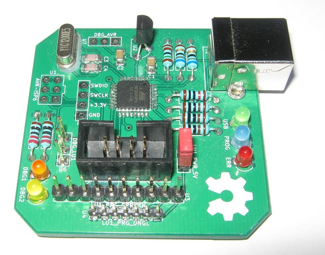
It has connectors with pin configurations which allow two popular nRF24LU1+ breakouts and dongles to be directly plugged into the flasher. One is the SparkFun Tranciever Breakout - nRF24LU1+, and the other is the popular nRF USB dongle from ebay.
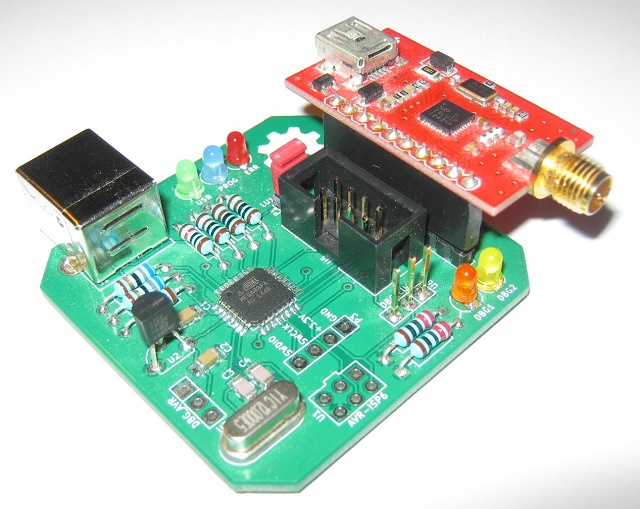
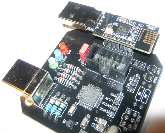
It also has an 8 pin flat cable connector through which it can flash nRF24LE1 devices as an in-system programmer.
The DBG_LU1 output can be used as a UART debug output from the nRF24LU1+ dongle. There are also two LEDs (DBG1 and DBG2) which can be driven from the SparkFun breakout. This is also useful for debugging.
The flasher firmware communicates with the host PC though obdev's V-USB. It accepts commands from the PC, executes them and sends responses.
The program running on the host PC is a cross-platform (Windows and Linux) command line tool. It does not need special OS drivers because all communication is done through the USB HID class. It's been tested on Windows 7, 8 and 10 and on Linux running on Hardkernel's Odroid X2 board.
| Qty | Value | Footprint | References |
|---|---|---|---|
| 5 | 1K | nrfburn:Resistor_Horizontal_RM10mm | R5, R6, R7, R8, R9 |
| 2 | 18pF | nrfburn:c_1206 | C3, C4 |
| 2 | 1uF | nrfburn:c_1206 | C1, C2 |
| 2 | 68R | nrfburn:Resistor_Horizontal_RM10mm | R1, R2 |
| 1 | 10K | nrfburn:Resistor_Horizontal_RM10mm | R4 |
| 1 | 12MHz | nrfburn:Crystal_HC49-U_Vertical | X1 |
| 1 | 1K5 | nrfburn:Resistor_Horizontal_RM10mm | R3 |
| 1 | ATMEGA88PA-AU | nrfburn:TQFP32 | IC1 |
| 1 | AVR-ISP6 | nrfburn:AVR_ISP6 | U1 |
| 1 | DBG1 | nrfburn:LED-3MM | D4 |
| 1 | DBG2 | nrfburn:LED-3MM | D5 |
| 1 | DBG_AVR | nrfburn:Pin_Header_Straight_1x03 | U7 |
| 1 | DBG_LU1 | nrfburn:Pin_Header_Straight_1x03 | U6 |
| 1 | ERR | nrfburn:LED-3MM | D2 |
| 1 | LE1_PRG | nrfburn:NRF_ICSP_RibbonCable | U5 |
| 1 | LU1_PRG_DNGL | nrfburn:LU1_PRG_DONGLE | U4 |
| 1 | LU1_PRG_SPRKFN | nrfburn:Pin_Header_Straight_1x10 | U3 |
| 1 | MCP1702 | nrfburn:SOT23 | U2 |
| 1 | OSHW-logo_silkscreen-back_9mm | nrfburn:OSHW-logo_silkscreen-back_9mm | G*** |
| 1 | OSHW-logo_silkscreen-front_12mm | nrfburn:OSHW-logo_silkscreen-front_12mm | G*** |
| 1 | PROG | nrfburn:LED-3MM | D1 |
| 1 | PWR_5V | nrfburn:Pin_Header_Straight_1x02 | P1 |
| 1 | SWD | nrfburn:Pin_Header_Straight_1x04 | P3 |
| 1 | USB | nrfburn:LED-3MM | D3 |
| 1 | USB_B | nrfburn:USB_B_loc | P2 |
It measures 50 × 50 mm and has 2 copper layers, 1.6 mm thick.
32 parts, built around the ATMEGA88PA-AU. The full list of its parts is on this page, with links to each part's symbol and footprint where PCBKit's library has them.
From the nodep/nrfburn repository on GitHub, at the commit this page was made from: the board is circuit/KiCAD_v1.2/nrfburn.kicad_pcb and its schematic circuit/KiCAD_v1.2/nrfburn.kicad_sch. PCBKit opens the board in the browser, with nothing to install.
Its repository publishes it under the GPL-3.0 licence: you may reuse it on that licence's terms (keep the author's notice, and for a copyleft licence share your changes alike).

jsanpe/SwinsidNeat
Yet another PCB layout of the nano SwinSID focusing on aesthetics

hackup/NanoSwinSIDc
Simple AVR-based replacement for the MOS6581 and MOS8580 sound chips aka. the Commodore SID.


vpatkov/continuity-tester
Ultra low-voltage, low-current, and fast continuity tester


