2 layers66 × 99.1 mm

 vpatkov/continuity-tester2
Ultra low-voltage, low-current, and fast continuity tester
Continuity tester is an open-source printed circuit board by vpatkov, from the vpatkov/continuity-tester repository on GitHub. It is a 2-layer board of 52.1 × 65.4 mm with 38 parts on 39 nets, routed with 238 tracks and 36 vias.
It is built around the ATMEGA88PA-AU, MCP6V61-E/OT and TLV431ASN, with the BAV199, BAS316 and CR2032 among its other parts. Its parts include 17 resistors, 6 capacitors, 4 diodes, 3 ICs and 3 connectors. It belongs with the AVR (ATmega, ATtiny) boards of this library.


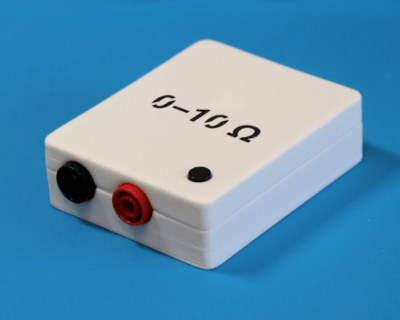
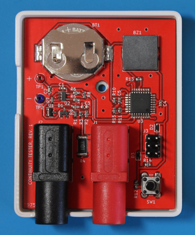
Ultra low-voltage, low-current, and fast continuity tester.
Open circuit voltage is 100 mV, short circuit current is 100 μA. No risk of damaging sensitive components. Keep semiconductor junctions closed. Multimeters usually apply much higher voltage and current to the probes (and not always specified).
Resistance-dependent beeper tones with chromatic steps. Allows to differentiate resistance by ear. The range is 0–10 Ω with 1 Ω steps. Multimeters usually have a pretty big threshold and require you to look at the screen to read the resistance, e.g., to catch a bad connection.
Detects shorts of 150 μs. Minimal beep duration is 100 ms (latching). Suitable for finding connections by sweeping and brushing without the risk of missing a beep. Gold-plated probes are recommended.
Inverted mode. If probes are shorted during power-on, the tester turns into inverted mode: silent for < 10 Ω, beeps otherwise. Beeps are still latched for 100 ms to not miss them. If normal mode is to find shorts, inverted mode is to find opens, e.g., intermittent bad connections, even very brief.
Auto-hold the minimal resistance (in normal mode). Helps against unstable contacts, e.g., on dirty, oxidized, or lacquered boards. The hold resets when the resistance becomes greater than 10 Ω.
200 working hours on a single CR2032 cell. The tester consumes approximately 1 mA. After 5 minutes of inactivity it turns off automatically.
30 V continuous input protection. The tester should not be used on a powered circuit, but just in case. Also saves against charged capacitors. The input impedance of the tester is 1 kΩ, so the risk of damaging an accidentally powered circuit under test is also low.
Quick self-test on power-on. Ensures the ADC, reference, and battery are fine. In case of failure, the tester beeps shortly two times and turns off.
| Multimeter | Open circuit voltage, V | Short circuit current, mA | Capture time, ms | Threshold, Ω |
|---|---|---|---|---|
| Keysight 34461A | (9.4) | 1 | ≤ 3.3 | 10 |
| Keysight 34401A | (7.0) | 1 | ≤ 3.3 | 1–1000 (adjustable) |
| Keysight U1282A | ≤ 2.7 | (1) | ≤ 1 | 25±11 |
| Fluke 8846A | (6.2) | 1 | ≤ 3.3 | 1, 10, 100, 1000 (selectable) |
| Fluke 45 | ≤ 3.2 | 0.7 | ≤ 0.05 | 30 |
| Fluke 117 | ≤ 2.7 | ≤ 0.35 | ≤ 0.5 | 20–250 (hysteresis) |
| Fluke 179 | ≤ 8.0 | ≤ 1.1 | ≤ 0.25 | 25–250 (hysteresis) |
| Fluke 289 | 5 | 1 | ≤ 1 | 40 (depends on range) |
| Fluke 87V | ≤ 7.9 | 1 | ≤ 1 | (?) |
| Brymen BM235 | (1.7) | (0.16) | ≤ 15 | Between 30 and 480 |
| Brymen BM869s | (2.9) | (0.38) | ≤ 0.1 | Between 20 and 200 |
| Hioki DT4256 | ≤ 1.8 | 0.2 | ≤ 0.5 | 20–245 (hysteresis) |
| Hioki DT4282 | ≤ 2.5 | 0.64 | ≤ 10 | 20, 50, 100, 500 (selectable) |
| Rigol DM3068 | ≤ 8 | 1 | ≤ 3.3 | 1–2000 (adjustable) |
| Siglent SDM3065X | ≤ 8 | 1 | ≤ 3.3 | 1–2000 (adjustable) |
| This tester | 0.1 | 0.1 | ≤ 0.15 | 1–10 (different tones) |
Values in parentheses are not specified.

| Qty | Value | Footprint | References |
|---|---|---|---|
| 5 | 10k | Resistor_SMD:R_0603_1608Metric | R1, R9, R13, R15, R16 |
| 4 | 100n | Capacitor_SMD:C_0603_1608Metric | C2, C4, C5, C6 |
| 3 | 1k | Resistor_SMD:R_0603_1608Metric | R5, R6, R14 |
| 2 | 100 | Resistor_SMD:R_0603_1608Metric | R7, R10 |
| 2 | BAV199 | Package_TO_SOT_SMD:SOT-23 | D1, D2 |
| 1 | 0 | Resistor_SMD:R_0603_1608Metric | R17 |
| 1 | 1.1k | Resistor_SMD:R_2512_6332Metric | R4 |
| 1 | 10 | Resistor_SMD:R_0603_1608Metric | R11 |
| 1 | 100p | Capacitor_SMD:C_0603_1608Metric | C1 |
| 1 | 12.4k | Resistor_SMD:R_0603_1608Metric | R3 |
| 1 | 1n | Capacitor_SMD:C_0603_1608Metric | C3 |
| 1 | 30k | Resistor_SMD:R_0603_1608Metric | R12 |
| 1 | 5.1k | Resistor_SMD:R_0603_1608Metric | R2 |
| 1 | 560k | Resistor_SMD:R_0603_1608Metric | R8 |
| 1 | ATmega88PA-A | Package_QFP:TQFP-32_7x7mm_P0.8mm | U3 |
| 1 | AVR ISP | Connector_PinHeader_2.54mm:PinHeader_2x03_P2.54mm_Vertical | J3 |
| 1 | BAS316 | Diode_SMD:D_SOD-323 | D3 |
| 1 | Banana | Connector:Banana_Cliff_FCR7350B_S16N-PC_Horizontal | J2 |
| 1 | Banana | Connector:Banana_Cliff_FCR7350R_S16N-PC_Horizontal | J1 |
| 1 | Button | Button_Switch_THT:SW_PUSH_6mm | SW1 |
| 1 | CR2032 | Battery:BatteryHolder_Keystone_3034_1x20mm | BT1 |
| 1 | IRLML6402 | Package_TO_SOT_SMD:SOT-23 | Q1 |
| 1 | MCP6V61 | Package_TO_SOT_SMD:SOT-23-5 | U2 |
| 1 | PESD3V3U1UA | Diode_SMD:D_SOD-323 | D4 |
| 1 | PKLCS1212E4001 | Buzzer_Beeper:Buzzer_Murata_PKLCS1212E | BZ1 |
| 1 | TLV431 | Package_TO_SOT_SMD:SOT-23 | U1 |
The 37 most common of 38 parts.
It measures 52.1 × 65.4 mm and has 2 copper layers, 1.6 mm thick.
38 parts, built around the ATMEGA88PA-AU, MCP6V61-E/OT, TLV431ASN and BAV199. The full list of its parts is on this page, with links to each part's symbol and footprint where PCBKit's library has them.
From the vpatkov/continuity-tester repository on GitHub, at the commit this page was made from: the board is pcb/ct.kicad_pcb and its schematic pcb/ct.kicad_sch. PCBKit opens the board in the browser, with nothing to install.
Its repository states no licence, so its author keeps all rights: ask vpatkov before reusing the design.


Lelk0e/DA_Sensorbox
Diplomarbeit 2024-2025 mit der Firma B2 electronics. Das Ziel ist es eine Sensorbox mit dem ESP32, als Basis zu entwickeln. Diese Sensorbox soll über ein Mesh-Netzwerk erweiterbar werden.

Alli-Ekundayo/scpt-rl
SCPT-RL trains a cross-attention transformer policy to place PCB components sequentially on a discrete grid. Training has two phases:


Global-Health-Engineering/h2s-monitor
Design and Development of a Low-Cost Hydrogen Sulfide Sensor System for Biogas Monitoring

yoichiro/lunakey
Lunakey - This is a brand for keyboards designed by Yoichiro Tanaka.
