2 layers52.1 × 65.4 mm
Continuity tester
vpatkov/continuity-tester
Ultra low-voltage, low-current, and fast continuity tester
38 parts2

 vpatkov/esr-meter5
AC ohmmeter
Esr meter is an open-source printed circuit board by vpatkov, from the vpatkov/esr-meter repository on GitHub. It is a 2-layer board of 66 × 99.1 mm with 105 parts on 86 nets, routed with 517 tracks and 151 vias.
It is built around the ATMEGA88PA-AU, OPA1678ID and MCP73831, with the TLV431ASN, TPS60403 and DTC114E among its other parts. Its parts include 44 resistors, 24 capacitors, 11 diodes, 9 transistors and 8 ICs. It belongs with the AVR (ATmega, ATtiny) boards of this library.


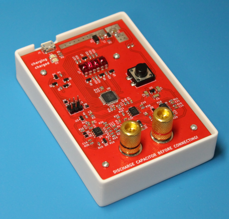
This device measures impedance at 100 kHz in assumption it's resistive1, basically an AC ohmmeter. Not for laboratory measurements, but for troubleshooting. The main usage is to find dried out electrolytic capacitors in aged electronics. Also may be used for continuity testing in a circuit containing inductors or transformers (it may be hard to distinguish a short from a winding at DC), or for finding shorted windings.
Some specs:
To switch the meter on or off, press the button. After 3 minutes of inactivity the meter switched off automatically.
On startup, the meter performs a self-test. Keep the terminals open. During the test, the meter turns on all the segments on the display, then shows an error if any:
E.F.LO: low fuel (battery voltage < 3.3 V);E.rEF: something wrong with voltage references or ADC;E.Prb: something wrong with the test signal (or the terminals aren't open).When the test is passed, the meter shows the current battery level in percents
as F <level>.
During normal operation the meter continuously shows the measured impedance in Ω,
or -OL- if it's more than 99.99 Ω.
Note that inductance of test leads matters at 100 kHz. You should connect capacitors directly to the binding post, or use leads as short as possible.
Unless otherwise noted, this work is licensed under Creative Commons Zero 1.0.

The readings corresponds to a resistance that gives the same amplitude drop of the test signal as the device under test. ↩
| Qty | Value | Footprint | References |
|---|---|---|---|
| 11 | 100n | Capacitor_SMD:C_0603_1608Metric | C3, C8, C16, C17, C18, C19, C20, C21, C22, C23, C24 |
| 8 | 10 | Resistor_SMD:R_0603_1608Metric | R35, R36, R38, R39, R41, R42, R43, R44 |
| 8 | 2.4k | Resistor_SMD:R_0603_1608Metric | R27, R28, R29, R30, R31, R32, R33, R34 |
| 7 | DTC114E | Package_TO_SOT_SMD:SOT-23 | Q1, Q3, Q4, Q6, Q7, Q8, Q9 |
| 5 | 10k | Resistor_SMD:R_0603_1608Metric | R5, R8, R9, R10, R18 |
| 5 | 1k | Resistor_SMD:R_0603_1608Metric | R14, R15, R19, R26, R37 |
| 5 | BAS316 | Diode_SMD:D_SOD-323 | D4, D5, D6, D7, D9 |
| 4 | 10n | Capacitor_SMD:C_0603_1608Metric | C7, C9, C10, C15 |
| 3 | 1n | Capacitor_SMD:C_0603_1608Metric | C12, C13, C14 |
| 3 | 1μ | Capacitor_SMD:C_1206_3216Metric | C2, C4, C5 |
| 3 | 33k | Resistor_SMD:R_0603_1608Metric | R1, R6, R22 |
| 3 | OPA1678 | Package_SO:SO-8_3.9x4.9mm_P1.27mm | U4, U5, U8 |
| 2 | 1.58k | Resistor_SMD:R_0603_1608Metric | R17, R23 |
| 2 | 100k | Resistor_SMD:R_0603_1608Metric | R12, R13 |
| 2 | 3k | Resistor_SMD:R_0603_1608Metric | R3, R4 |
| 2 | 4.7μ | Capacitor_SMD:C_1206_3216Metric | C1, C6 |
| 2 | SM4007 | Diode_SMD:D_MELF | D10, D11 |
| 1 | 10 | Resistor_SMD:R_0805_2012Metric | R25 |
| 1 | 100 | Resistor_SMD:R_0603_1608Metric | R11 |
| 1 | 2.2k | Resistor_SMD:R_0603_1608Metric | R21 |
| 1 | 3.3M | Resistor_SMD:R_0603_1608Metric | R20 |
| 1 | 3.3k | Resistor_SMD:R_0603_1608Metric | R2 |
| 1 | 31.6k | Resistor_SMD:R_0603_1608Metric | R7 |
| 1 | 45.3k | Resistor_SMD:R_0603_1608Metric | R40 |
| 1 | 499 | Resistor_SMD:R_0805_2012Metric | R24 |
| 1 | ATmega88PA-AU | Package_QFP:TQFP-32_7x7mm_P0.8mm | U6 |
| 1 | BAT54J | Diode_SMD:D_SOD-323F | D8 |
| 1 | Binding Post | esr-meter:BindingPost | J4 |
| 1 | DNP | Capacitor_SMD:C_0603_1608Metric | C11 |
| 1 | DNP | Resistor_SMD:R_0603_1608Metric | R16 |
| 1 | GREEN | LED_SMD:LED_1206_3216Metric | D3 |
| 1 | IRLML6402 | Package_TO_SOT_SMD:SOT-23 | Q2 |
| 1 | JST-XH | Connector_JST:JST_XH_S2B-XH-A-1_1x02_P2.50mm_Horizontal | J2 |
| 1 | MCP73831 | Package_TO_SOT_SMD:SOT-23-5 | U1 |
| 1 | MMBFJ113 | Package_TO_SOT_SMD:SOT-23 | Q5 |
| 1 | Pin Header Male | Connector_PinHeader_2.54mm:PinHeader_2x03_P2.54mm_Vertical | J3 |
| 1 | QDSP-6064 | Package_DIP:DIP-12_W7.62mm | U7 |
| 1 | RED | LED_SMD:LED_1206_3216Metric | D2 |
| 1 | SMAJ5.0A | Diode_SMD:D_SMA | D1 |
| 1 | SW_Push | Button_Switch_THT:SW_PUSH-12mm_Wuerth-430476085716 | SW1 |
| 1 | TLV431 | Package_TO_SOT_SMD:SOT-23 | U3 |
| 1 | TPS60403 | Package_TO_SOT_SMD:SOT-23-5 | U2 |
| 1 | USB_B_Micro | Connector_USB:USB_Micro-B_Molex-105017-0001 | J1 |
The 101 most common of 105 parts.
It measures 66 × 99.1 mm and has 2 copper layers, 1.6 mm thick.
105 parts, built around the ATMEGA88PA-AU, OPA1678ID, MCP73831 and TLV431ASN. The full list of its parts is on this page, with links to each part's symbol and footprint where PCBKit's library has them.
From the vpatkov/esr-meter repository on GitHub, at the commit this page was made from: the board is hardware/esr-meter.kicad_pcb and its schematic hardware/analog.kicad_sch. PCBKit opens the board in the browser, with nothing to install.
Its repository states no licence, so its author keeps all rights: ask vpatkov before reusing the design.
vpatkov/continuity-tester
Ultra low-voltage, low-current, and fast continuity tester

Oleg-mk/MOST25-to-AUDIO
Passive MOST25 listener: Tang Nano 20K FPGA, ESP32 host, stereo I2S out with the head unit's volume, balance and tone


ribbotson/OpenBCI_ESP32
Clone of OpenBCI Brain Computer Interface Hardware using ESP32 Processor