2 layers236.8 × 129.1 mm
CoCoTANG
lfantoniosi/CoCoTANG
CoCoTANG upgrades the Radio Shack/Tandy Color Computer with a Tang Nano 20K FPGA board and CoCo 3 video and memory features.
127 parts12
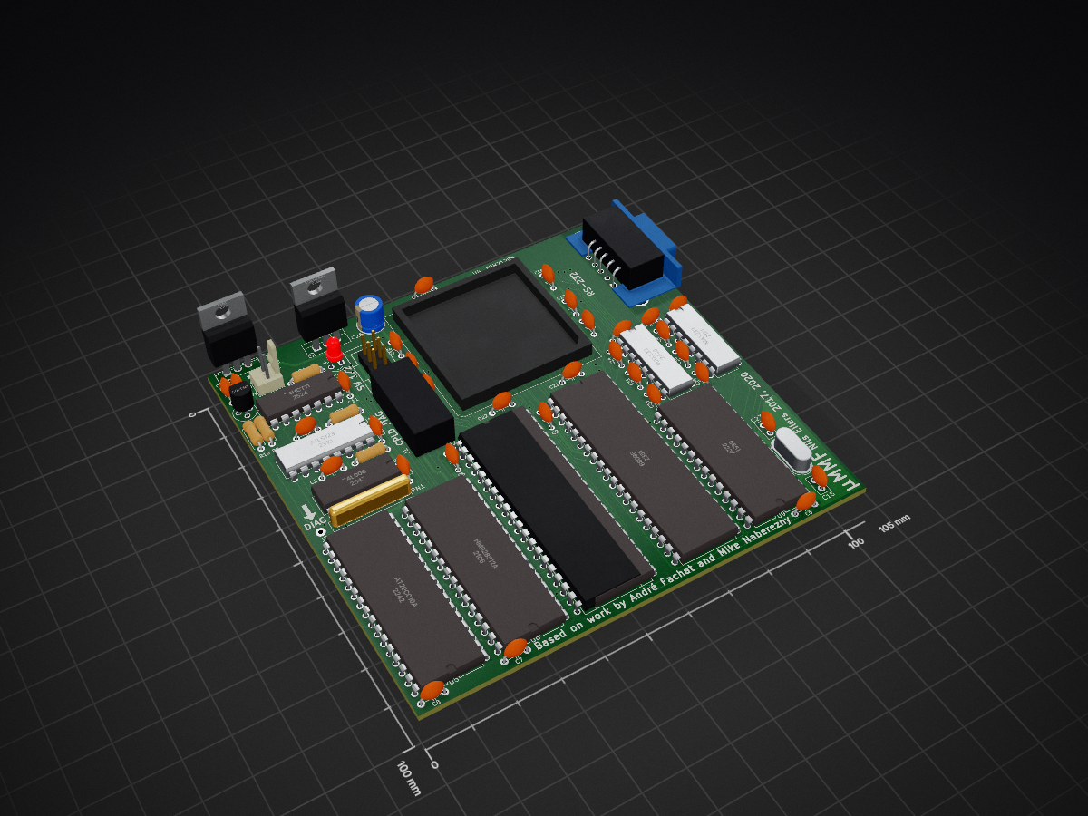
 nils-eilers/uMMF10
Upgrades your CBM 8032 to a SuperPET
Superpet is an open-source printed circuit board by nils-eilers, from the nils-eilers/uMMF repository on GitHub. It is a 2-layer board of 105 × 100 mm with 66 parts on 139 nets, routed with 2,076 tracks and 76 vias.
It is built around the MAX232N, 74HCT11D and 74LS123FP-E, with the AT29C010A and HM628512ALFP among its other parts. Its parts include 33 capacitors, 13 ICs, 6 connectors, 5 resistors and 2 switches. It belongs with the FPGA and CPLD boards of this library.


The SuperPET is basically a Commodore CBM 8032 with two, later only one extra boards in it which contain a 6809 CPU, 64 KB RAM and some ROMs. This project aims to provide a replacement for these extra board(s) with slightly more modern parts, enabling every CBM 8032 owner to upgrade his machine to a SuperPET.
This board requires a NMOS 6502. Do NOT use a CMOS 6502!
The board will accept NMOS Motorola 6809E as well as CMOS Hitachi HD63C09E, just ensure you get the E-type, not those without appended ‘E’ because their pinout is different. The version without E has the clock generator integrated, the E-version requires an external clock generator.
LED D1 is a low current (2 mA) type. It is used solely for debug purposes, the original SuperPET does not contain such a LED, so you may omit it.
IC3 74HCT11 has to be a HCT type. Do not use HC, LS or anything else because HCT was chosen to match the voltage level requirements.
Please note that some modifications on the original CBM 8032 motherboard must been made, as on the original SuperPET boards:
Refer to the pictures provided in the doc subdirectory for information about how to provide the 16 MHz clock signal at pin 35. These differ slightly from board version to board version.
An Atmel AT29C010 Flash ROM is required, programmed with roms/superpet.bin and write protected.
The CPLD code was written in Verilog. These were my first steps with Verilog, so please bear with me. Use Altera Quartus II 13.0.1 SP1 to compile the Verilog and program the CPLD, newer versions don't support the MAX7000 CPLD series any longer. The binary to program the CPLD is located at cpld/output_files/superpet.pof.
An interactive bill of materials is available at bom/ibom.html
| Qty | Value | Footprint | References |
|---|---|---|---|
| 11 | 1uF | eilers4:C_Disc_D5.0mm_W2.5mm_P5.00mm | C4, C14, C24, C28, C29, C30, C31, C32, C33, C34, C35 |
| 9 | 100nF | eilers4:C_Disc_D5.0mm_W2.5mm_P5.00mm | C5, C6, C7, C8, C9, C10, C11, C12, C25 |
| 7 | 220nF | eilers4:C_Disc_D5.0mm_W2.5mm_P5.00mm | C16, C17, C18, C19, C20, C21, C22 |
| 3 | Pin_Headers:Pin_Header_Straight_1x01_Pitch2.54mm | H1, H2, H3 | |
| 3 | 10nF | eilers4:C_Disc_D5.0mm_W2.5mm_P5.00mm | C1, C2, C3 |
| 2 | 22k | Resistors_THT:R_Axial_DIN0207_L6.3mm_D2.5mm_P7.62mm_Horizontal | R6, R7 |
| 2 | 22pF | Capacitors_THT:C_Disc_D5.0mm_W2.5mm_P2.50mm | C15, C27 |
| 2 | MAX232 | eilers4:DIP-16_W7.62mm | U8, U11 |
| 1 | 1.8432 MHz, HC49U | Crystals:Crystal_HC49-U_Vertical | X1 |
| 1 | 100 µF | Capacitors_THT:CP_Radial_D6.3mm_P2.50mm | C26 |
| 1 | 1k5 | Resistors_THT:R_Axial_DIN0207_L6.3mm_D2.5mm_P7.62mm_Horizontal | R10 |
| 1 | 2N4403 | eilers4:TO-92 | Q1 |
| 1 | 510R | Resistors_THT:R_Axial_DIN0207_L6.3mm_D2.5mm_P7.62mm_Horizontal | R9 |
| 1 | 6 x 3k3 | eilers4:R_Array_SIP7 | RN1 |
| 1 | 6502 | eilers4:DIP-40_W15.24mm | U1 |
| 1 | 6502 socket | eilers4:DIP-40_W15.24mm | J2 |
| 1 | 6551 | eilers4:DIP-28 | U9 |
| 1 | 680 | Resistors_THT:R_Axial_DIN0207_L6.3mm_D2.5mm_P7.62mm_Horizontal | R1 |
| 1 | 6809E | eilers4:DIP-40_W15.24mm | U2 |
| 1 | 74HCT11 | eilers4:DIP-14_W7.62mm | U3 |
| 1 | 74LS06 | eilers4:DIP-14_W7.62mm | U7 |
| 1 | 74LS123 | eilers4:DIP-16_W7.62mm | U10 |
| 1 | 7805 | TO_SOT_Packages_THT:TO-220-3_Vertical | U14 |
| 1 | AT29C010A | eilers4:DIP-32-15.24 | U5 |
| 1 | CPU Select | eilers4:WSL_6W_HALF | SW2 |
| 1 | Conn_01x01 | Wire_Pads:SolderWirePad_single_1mmDrill | J3 |
| 1 | Conn_01x02 | Connectors_Molex:Molex_KK-6410-02_02x2.54mm_Straight | J5 |
| 1 | Conn_02x05_Odd_Even | Connectors_Multicomp:Multicomp_MC9A12-1034_2x05x2.54mm_Straight | J8 |
| 1 | DB9_Male_MountingHoles | Connectors_DSub:DB9MC | J4 |
| 1 | EPM7128S | eilers4:PLCC-84_THT-Socket | U4 |
| 1 | HM628512A | eilers4:DIP-32-15.24 | U6 |
| 1 | JTAG | Connectors_Multicomp:Multicomp_MC9A12-1034_2x05x2.54mm_Straight | J1 |
| 1 | LED | LEDs:LED_D3.0mm | D1 |
| 1 | TSR 1-2450 | TO_SOT_Packages_THT:TO-220-3_Vertical | U12 |
| 1 | Write Protect | eilers4:WSL_6W_HALF | SW1 |
It measures 105 × 100 mm and has 2 copper layers, 1.6 mm thick.
66 parts, built around the MAX232N, 74HCT11D, 74LS123FP-E and AT29C010A. The full list of its parts is on this page, with links to each part's symbol and footprint where PCBKit's library has them.
From the nils-eilers/uMMF repository on GitHub, at the commit this page was made from: the board is kicad/superpet.kicad_pcb. PCBKit opens the board in the browser, with nothing to install.
Its repository states no licence, so its author keeps all rights: ask nils-eilers before reusing the design.
lfantoniosi/CoCoTANG
CoCoTANG upgrades the Radio Shack/Tandy Color Computer with a Tang Nano 20K FPGA board and CoCo 3 video and memory features.


AJain9199/AOS16
Table of Contents About The Project Pictures Technical Details Directory Structure To-Do Acknowledgments

barberd/coco9511pak
This board is a cartridge for the Tandy Radio Shack TRS-80 Color Computer (CoCo), an 8 bit computer produced between 1980 and 1991. It provides an Arithmetic Processor Unit (APU), the AMD 9511, to the CoCo.


RetroStack/Sorcerer_DreamDisk
Exidy Sorcerer/MicroBee DreamDisk Disk Controller