Skip to the content
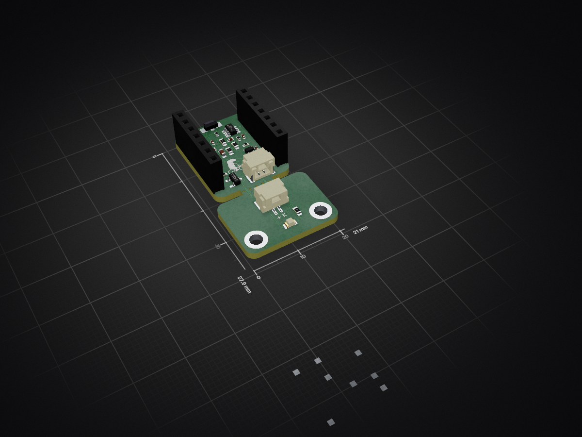
2 layers21 × 37.9 mmIr spoke link.layout, the printed circuit board in 3D

Configurable 940 nm IR spoke sensor with KiCad 10 hardware, linked Python/ngspice simulation, ESP-IDF RMT firmware, and JLCPCB exports.

Size
21 × 37.9 mm
Copper layers
2
Thickness
1.6 mm
Parts
45
Nets
28
Pads
100
Tracks, vias
197, 12
Pours
1
Routed
Yes
KiCad
KiCad 10.0 (file 20260206)
Created
31 Jul 2026
Updated
19 Aug 2026

Overview

Ir spoke link.layout is an open-source printed circuit board by niklasdathe, from the niklasdathe/IRBicycleWheelSpeedSensor repository on GitHub. It is a 2-layer board of 21 × 37.9 mm with 45 parts on 28 nets, routed with 197 tracks and 12 vias.

It is built around the CC0402JRNPO9BN121, 0603WAF1602T5E (SMT业务专用) and 0402B102K500NT, with the 0402CG4R7C500NT, SM02B-GHS-TB(LF)(SN) and S8050 among its other parts. Its parts include 11 resistors, 6 capacitors, 4 connectors, 2 ICs and 2 diodes. It belongs with the sensors and measurement boards and the ESP32 boards of this library.

Main components

8

README

README.md

IR Spoke Sensor

Repository checks Documentation Hardware release

Configurable 940 nm through-beam spoke sensor for a Seeed Studio XIAO ESP32-S3. A discrete analog front end restores a 25-50 kHz optical carrier; ESP-IDF RMT detects its interruption and learns the wheel's spoke pattern.

This repository is the wheel-speed-sensor subsystem of BicycleOBU. The online Interactive BOM is generated directly from the authoritative KiCad PCB.

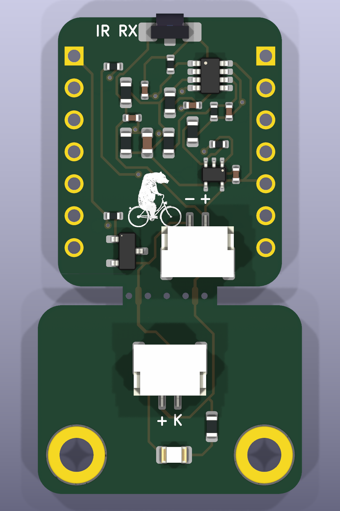
Hardware V0.1 receiver and breakaway emitter panel

Status

Hardware V0.1 (KiCad CAD revision R4) was ordered and is preserved as a GitHub release. main is now hardware V0.2-dev; physical validation is still open for V0.1.

AreaCurrent evidence
HardwareKiCad 10 ERC: 0 errors, 3 known library-sync warnings; DRC: 0 violations, 0 unconnected pads
Connectivity70 schematic endpoints, PCB pad nets and SPICE topology cross-checked
SimulationPython transient, 10,000-case sweep and ngspice cross-check pass
FirmwarePortable core, RMT/CAN adapters and BLE CSC component implemented; ESP32-S3 target build passes, HIL pending
ManufacturingVersioned JLC Gerber/BOM/CPL package generated; assembly-preview approval pending
Physical performanceSunlight, alignment, contamination, vibration and power tests pending

Do not treat simulation as production validation. The remaining gates are listed in TODO.md.

Start here

GoalGuide
Understand the signal chainSystem overview
Open the design or run the simulatorGetting started
Change configuration, firmware or captured CADDevelopment workflow
Order or review the PCBManufacturing
Inspect or place componentsInteractive BOM
Bring up and correlate a prototypeBring-up and test
Trace a requirement to evidenceVerification matrix
Find a technical referenceDocumentation index

Hardware V0.1 at a glance

PropertyV0.1 value
Optical path940 nm VSMB1940X01 emitter to VEMD10940FX01 photodiode
Carrier25-50 kHz runtime range; 38 kHz default; 50% duty
ReceiverTLV9062 TIA/band-pass, TLV7011 Schmitt comparator
MCU interfaceGPIO1 RMT TX, GPIO2 RMT RX with carrier demodulation
Wheel design range16-48 spokes; 60 km/h requirement, 80 km/h stress calculation
Receiver outline17.8 x 21.4 mm XIAO outline
Emitter outline21 x 15 mm, two M2.5 holes
PanelTwo-layer PCB with one routed mouse-bite breakaway tab
Remote link600 mm two-conductor JST-GH harness after snap-off
Optional interfaceOfficial XIAO MCP2515 CAN expansion; disabled by default
BLE interfaceWheel-only Bluetooth Cycling Speed and Cadence Sensor (0x1816)

One-command entry points

powershell
.\Open-IR-Spoke-Sensor.cmd
.\Open-Interactive-BOM.cmd
py -3.14 simulation\local_server.py
powershell -ExecutionPolicy Bypass -File tests\run_all.ps1
powershell -ExecutionPolicy Bypass -File hardware\export_jlc.ps1 -Revision V0.2

The KiCad launcher also starts the InteractiveHtmlBom watcher at http://127.0.0.1:8766/; every complete PCB save regenerates and reloads the browser view. The simulator opens at http://127.0.0.1:8765/. Disposable simulation evidence is written under ignored build/.

Source of truth

ConcernAuthoritative source
Tunable system valuesconfig/system.json
Pins and electrical netshardware/connectivity.json
Parts, fields and procurementhardware/component_catalog.json
Captured schematic and routinghardware/ir_spoke_link/layout_manifest.json
Requirementsrequirements/requirements.yaml
Project paths and revisionproject_manifest.json
Hardware/software versionsdocs/versioning.md
Changes between releasesCHANGELOG.md

Generators restore the captured user layout and must not synthesize, remove or reroute tracks. See CONTRIBUTING.md before changing CAD or generated files.

License

No project license has been selected yet. Until one is added, the repository must not be presented as granting open-hardware, software or documentation reuse rights.

Parts

45
QtyValueFootprintReferences
5BREAKAWAY_NPTH_0.5Breakaway_MouseBite_0.5mmMB1, MB2, MB3, MB4, MB5
410kR_0603_1608MetricR3, R4, R7, R9
2100nC_0402_1005MetricC5, C6
2LOGOLOGOG***, G***
2MountingHole_2.7mm_M2.5_DIN965_Pad_TopBottomMountingHole:MountingHole_2.7mm_M2.5_DIN965_Pad_TopBottomMH1, MH2
2TEMP_BREAKAWAY_LINKNetTie-2_SMD_Pad0.5mmNT1, NT2
1+3V3TestPoint_Pad_D1.0mmTP2
1100RR_0402_1005MetricR11
1120pC_0402_1005MetricC2
116kR_0603_1608MetricR6
11MR_0402_1005MetricR10
11kR_0402_1005MetricR2
11nC_0402_1005MetricC3
11uC_0603_1608MetricC1
133kR_0402_1005MetricR5
139RR_0603_1608MetricR1
14.7pC_0402_1005MetricC4
1560kR_0402_1005MetricR8
1BANDPASSTestPoint_Pad_D1.0mmTP6
1COMP_OUTTestPoint_Pad_D1.0mmTP7
1GNDTestPoint_Pad_D1.0mmTP1
1JST GH LEDJST_GH_SM02B-GHS-TB_1x02-1MP_P1.25mm_HorizontalJ4
1RX_RMT_GPIO2TestPoint_Pad_D1.0mmTP8
1S8050SOT-23Q1
1TIA_OUTTestPoint_Pad_D1.0mmTP5
1TLV7011DCKRSOT-353_SC-70-5U2
1TLV9062IDDFRSOT-23-8U1
1TX CABLEJST_GH_SM02B-GHS-TB_1x02-1MP_P1.25mm_HorizontalJ3
1TX_CARRIER_GPIO1TestPoint_Pad_D1.0mmTP4
1VEMD10940FX01VEMD10940F_SideViewD2
1VREFTestPoint_Pad_D1.0mmTP3
1VSMB1940X01LED_0805_2012MetricD1
1XIAO_LEFTPinSocket_1x07_P2.54mm_VerticalJ1
1XIAO_RIGHTPinSocket_1x07_P2.54mm_VerticalJ2

Similar boards

  • 4 layers100 × 100 mmPhmod, the printed circuit board in 3D

    Phmod

    gallicchio/AMOD-and-RFMOD

    The tutorial's 2x12 adapter (/mudd/133electronics/icepi-zero-dac-adc/adapterboard/) with a 2 x 6 right-angle Pmod socket on a 15 mm extension of its right-hand end, so an Icepi Zero can drive AMOD-A's and RF-MOD's Pmod…

    234 parts
  • 4 layers220 × 120 mmCandidate filled profile, the printed circuit board in 3D

    Candidate filled profile

    misko/prompt2device

    The separate vNext PCB skill and orchestrator package is available alongside the reference workflow below; existing projects keep their accepted toolchain until an explicit migration.

    569 parts3MIT
  • 6 layers160 × 100 mmBuslab, the printed circuit board in 3D

    Buslab

    tombueng/hilprobe

    HILprobe: multi-function UUT probe for hardware-in-the-loop testing - RS-485, CAN FD, logic analyzer, 4-ch scope, two programmable UUT supplies. KiCad 10, 6 layers, RP2350B + ESP32-S3.

    429 parts
  • 6 layers50.2 × 77.2 mmMeko, the printed circuit board in 3D

    Meko

    KOEGlike/meko

    A linux music player with ddr3, a 70hz e-paper display and a haptic touchpad

    274 parts90GPL-3.0
  • 4 layers91 × 30.1 mmStrelka Flight Computer, the printed circuit board in 3D

    Strelka Flight Computer

    LulaUAV/Strelka-Flight-Computer

    Strelka exists in the family of rocket dog flight computers. This flight computer is fully capable of deploying recovery events.

    170 parts2
  • 2 layers100 × 81 mmBebop mb, the printed circuit board in 3D

    Bebop mb

    ballerabdude/bebop

    KiCad 10 project for the Bebop Connector / motherboard board. It is the interconnect between an NVIDIA Jetson Orin Nano carrier board, a Teensy 4.1 microcontroller, a Bosch BNO085 9‑DoF IMU (Adafruit breakout), and a…

    19 parts

Questions

How big is the Ir spoke link.layout PCB?

It measures 21 × 37.9 mm and has 2 copper layers, 1.6 mm thick.

What parts does the Ir spoke link.layout use?

45 parts, built around the CC0402JRNPO9BN121, 0603WAF1602T5E (SMT业务专用), 0402B102K500NT and 0402CG4R7C500NT. The full list of its parts is on this page, with links to each part's symbol and footprint where PCBKit's library has them.

Where can I download the Ir spoke link.layout KiCad files?

From the niklasdathe/IRBicycleWheelSpeedSensor repository on GitHub, at the commit this page was made from: the board is hardware/ir_spoke_link/ir_spoke_link.layout.kicad_pcb and its schematic hardware/ir_spoke_link/ir_spoke_link.kicad_sch. PCBKit opens the board in the browser, with nothing to install.

Can I use the Ir spoke link.layout design in my own project?

Its repository states no licence, so its author keeps all rights: ask niklasdathe before reusing the design.