
4 layers99.9 × 100 mm
Hermeslite
softerhardware/Hermes-Lite2
A second generation low-cost amateur HF software defined radio transceiver.
490 parts384
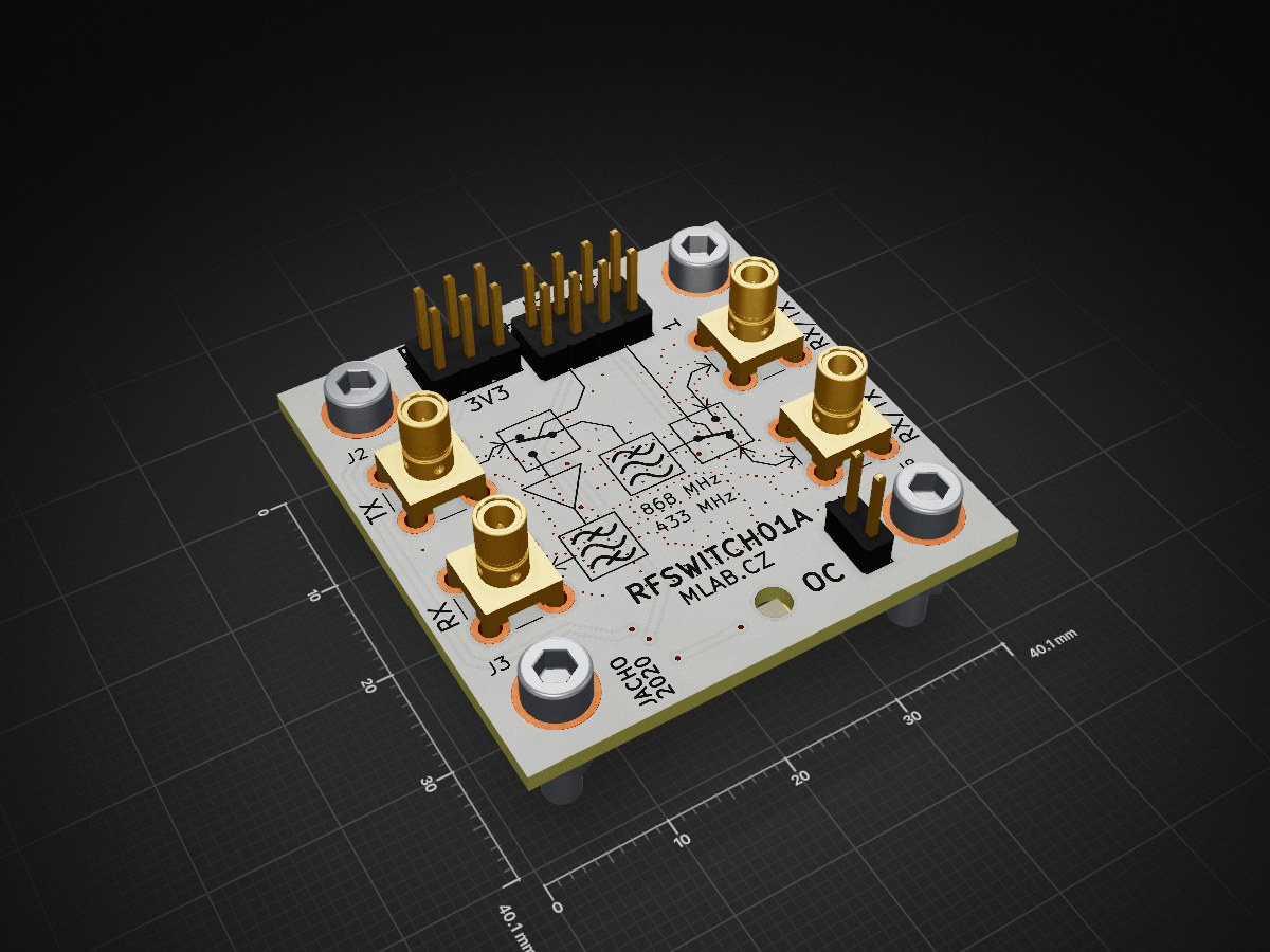
 mlab-modules/RFSWITCH01
The module featuring two RF switches. Designed for radio transceivers with separate input and output.
RFSWITCH01 is an open-source printed circuit board by mlab-modules, from the mlab-modules/RFSWITCH01 repository on GitHub, published under the GPL-3.0 licence. It is a 2-layer board of 40.1 × 40.1 mm with 45 parts on 23 nets, routed with 132 tracks and 290 vias.
It is built around the PE4259-63. Its parts include 10 capacitors, 10 connectors, 6 resistors, 6 inductors and 4 ICs. It belongs with the radio and wireless boards of this library.
The RFSWITCH01 is an MLAB module that incorporates a pair of RF switches, specifically the PE4259. from Peregrine Semiconductor. This module is designed to connect to a radio transceiver that has separate radio input and output. Thanks to the use of two switches, the module allows connecting two antennas. The individual switches are controlled by a simple digital input signal. With RFSWITCH01, a transceiver can work with the support of MIMO 2x2. The module is typically assembled for frequencies of 433MHz and 868MHz.
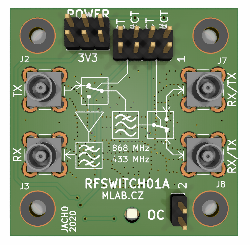
The RFSWITCH01 module can be used in a variety of applications where MIMO 2x2 support is required for a radio transceiver. This includes, but is not limited to:
For more detailed information about the PE4259 RF switch, please refer to the datasheet.
| Qty | Value | Footprint | References |
|---|---|---|---|
| 5 | 10k | Mlab_R:SMD-0805 | R1, R2, R3, R4, R5 |
| 5 | HEADER_2x01_PARALLEL | Mlab_Pin_Headers:Straight_2x01 | J4, J5, J6, J9, J10 |
| 4 | 1nF | Mlab_R:SMD-0805 | C5, C6, C7, C8 |
| 4 | HOLE | Mlab_Mechanical:MountingHole_3mm | M1, M2, M3, M4 |
| 4 | SMA | Connector_Coaxial:SMB_Jack_Vertical | J2, J3, J7, J8 |
| 2 | 100nH | Mlab_R:SMD-0805 | L4, L5 |
| 2 | 100pF | Mlab_R:SMD-0805 | C2, C4 |
| 2 | 2p2 | Mlab_R:SMD-0805 | C9, C10 |
| 2 | BZV55C-3,6V | Diode_SMD:D_MiniMELF | D2, D3 |
| 2 | PE4259 | Package_TO_SOT_SMD:SOT-363_SC-70-6 | U2, U4 |
| 1 | 100nF | Mlab_R:SMD-0805 | C3 |
| 1 | 100nH | Inductor_SMD:L_0805_2012Metric | L2 |
| 1 | 10uF | Mlab_R:SMD-0805 | C1 |
| 1 | 1n5H | Inductor_SMD:L_0805_2012Metric | L3 |
| 1 | 330R | Mlab_R:SMD-0805 | R6 |
| 1 | 6n8 | Mlab_R:SMD-0805 | L6 |
| 1 | 74279204 | Inductor_SMD:L_0805_2012Metric | L1 |
| 1 | HEADER_2x03_PARALLEL | Mlab_Pin_Headers:Straight_2x03 | J1 |
| 1 | M4 | Diode_SMD:D_SMA | D1 |
| 1 | RED | Mlab_D:LED_1206 | D4 |
| 1 | SAW_AFS434S3-T_AFS869S3-T | MLAB_SAW:ABRACON_AFS | FL1 |
| 1 | SPF5189Z | Package_TO_SOT_SMD:SOT-89-3 | U3 |
| 1 | TPS22945DCKR | Package_TO_SOT_SMD:SOT-353_SC-70-5 | U1 |
It measures 40.1 × 40.1 mm and has 2 copper layers, 1.6 mm thick.
45 parts, built around the PE4259-63. The full list of its parts is on this page, with links to each part's symbol and footprint where PCBKit's library has them.
From the mlab-modules/RFSWITCH01 repository on GitHub, at the commit this page was made from: the board is hw/sch_pcb/RFSWITCH01.kicad_pcb and its schematic hw/sch_pcb/RFSWITCH01.kicad_sch. PCBKit opens the board in the browser, with nothing to install.
Its repository publishes it under the GPL-3.0 licence: you may reuse it on that licence's terms (keep the author's notice, and for a copyleft licence share your changes alike).
softerhardware/Hermes-Lite2
A second generation low-cost amateur HF software defined radio transceiver.


Horizon-Avionics/Horizon-H1
Building a fully open-source flight computer for amateur rocketry!


Broccoliux/Black-Flipper
A device that out smart Flipper Zero in every aspect.

balcer/lora-modul
KiCAD project of 868MHz SEMTECH SX1276 LoRa module with SMA connector

MR-DOS/generator_5351_rect_sine
Rectangular and sine generator with Si5351 working up to 200 MHz

lucysrausch/sensor-implant
WIP hardware design files for a sensor implant for my bachelors thesis.