
2 layers124 × 112 mm

 micromouseonline/3020-software-spindle-control
PCB / code to make the PWM spindle control of a 3020 CNC machine work correctly
3020-cnc upgrade is an open-source printed circuit board by micromouseonline, from the micromouseonline/3020-software-spindle-control repository on GitHub. It is a 2-layer board of 69 × 29 mm with 15 parts on 37 nets, routed with 73 tracks and 0 vias.
It is built around the MCP41010-E/P. Its parts include 5 connectors, 3 ICs, 2 resistors and 1 diode. It belongs with the robots and motor control boards and the AVR (ATmega, ATtiny) boards of this library.
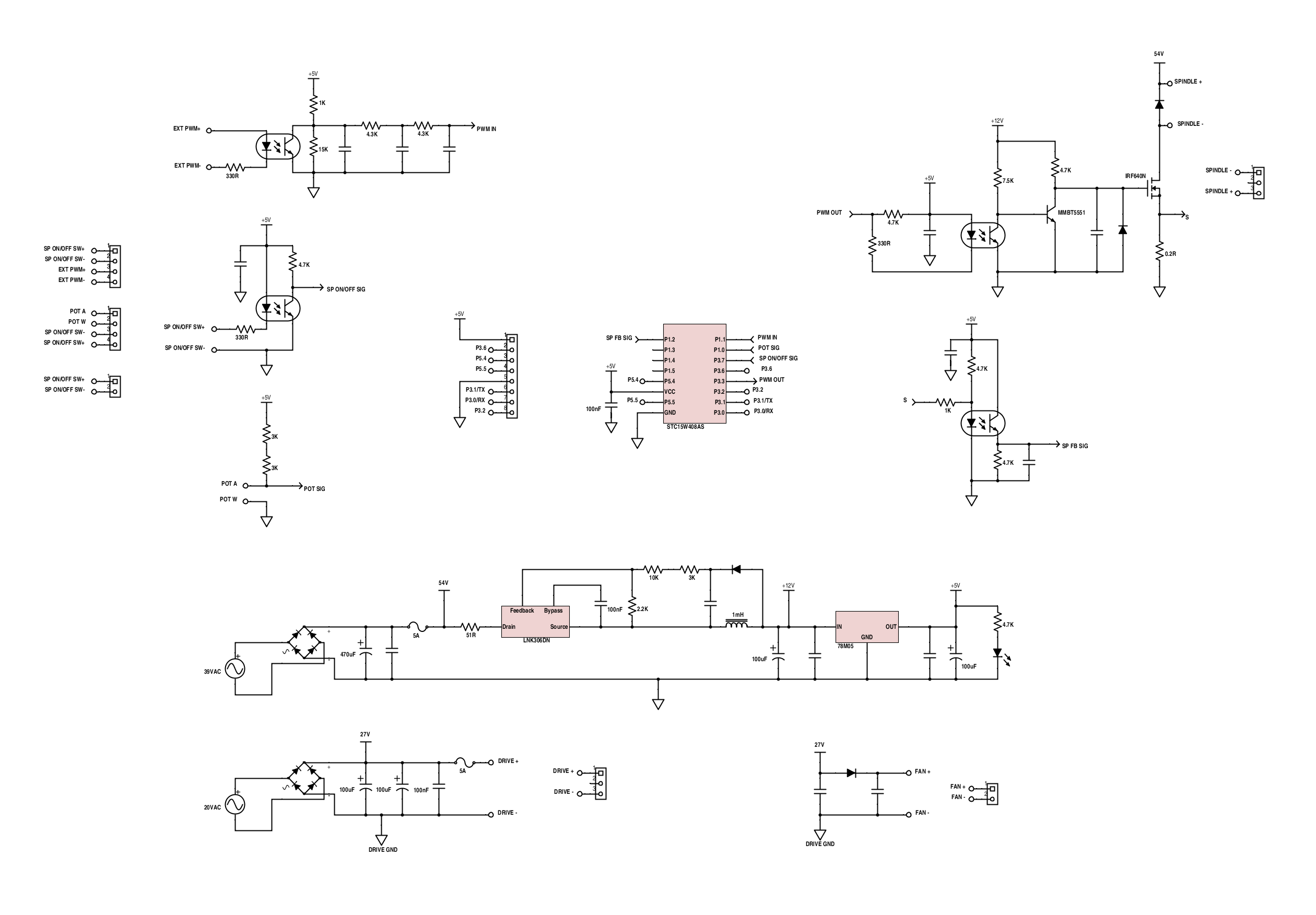
Thanks to Johnny from hackaday.io for his fantastic work reverse-engineering the JP-1481 spindle board, seen below:
You cannot control the spindle speed by any means other than the front panel knob.
This is particularly important in an emergency stop situation. While your controller will the stepper movement, the spindle will continue to spin.
The main interface (JP-382C) board routes pin 17 of the parallel port directly to the (unpopulated) "PWM OUT" connector on that board.
The JP-1482 (spindle control) board has a PWM input, but the firmware on the STC15W408AS (the MCU that ultimately controls spindle speed) does not respond to that input.
The solution is to use another MCU that reads from the existing front-panel knob, and the PWM from the interface board, that then simulates the front panel knob (using a programmable potentiometer).
The goal is to have a board you can simply plug in, and it just works.™
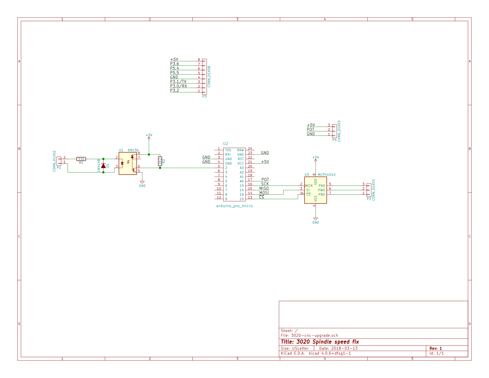
For the sake of ease, and getting up-and-running quickly, I opted to use an Arduino Pro Micro (5V), which I happened to have on hand.
The input PWM is buffered through a 6N136 opto isolator (since the PWM power supply is floating), and fed directly into the Arudino.
For output, there is an MCP41010 digital potentiometer, controlled via SPI. Since the front panel pot is 5K, we're only going to use ½ of it's 10K range.
Power (5v) is provided by the PWM board.
The software is standard Arduino code, though I'm using PlatformIO CLI since I'm not a big fan the Arduino IDE. Why not bare metal AVR? This isn't a demanding application, and while the Arduino ecosystem isn't the most efficient, it does make it quick and easy to get things up-and-running.
| Ref | P/N |
|---|---|
| P1 | B2B-XH-A(LF)(SN) |
| P2, P4 | B3B-XH-A(LF)(SN) |
| P3 | B8B-XH-A(LF)(SN) |
| R1 | Any 0802 330 ohm SMT resistor |
| R2 | Any 0802 2200 ohm SMT resistor |
| D1 | 1N4148 (optional) |
| U1 | 6N136, 8 DIP |
| U2 | Arduino Pro Micro (Ebay clone) |
| U3 | MCP41010, 8 DIP |
The connectors on the board are compatible with the connectors on the JP-1482; they're the JST XH series. Be careful buying random "XH" connectors from Ebay or even Amazon, for two reasons:
Buy genuine XH connectors and cables from a reputable supplier (e.g. Digi-key).
The board layout is rather tight. It's designed to have U1 and U3 soldered directly to the board, while U2 is in a socket, for ease of swapping, above the other ICs.
You may need to add the --upload-port parameter, depending on how your system enumerates the Arduino port.
cd 3020-software-spindle-control/fw
platformio run -t upload.hex file--- nothing here yet ---
The code will measure the input PWM from your controller, and monitors the front panel spindle control knob. The front panel knob sets the maximum speed. If this knob is at zero, the spindle will not be enabled. Example: if the knob is at the 60% position, and you command a 30% spindle speed via PWM, then the output speed will be 18% (0.3 x 0.6) of spindle absolute maximum speed. Also, the spindle on/off switch overrides everything else when in the off position.
| Qty | Value | Footprint | References |
|---|---|---|---|
| 2 | CONN_01X03 | Connectors_JST:JST_XH_B03B-XH-A_03x2.50mm_Straight | P2, P4 |
| 1 | 1N4148 | Diodes_SMD:SOD-123 | D1 |
| 1 | 2K2 | Resistors_SMD:R_0805 | R2 |
| 1 | 330 | Resistors_SMD:R_0805 | R1 |
| 1 | 6N136 | Housings_DIP:DIP-8_W7.62mm | U1 |
| 1 | CONN_01X02 | Pin_Headers:Pin_Header_Straight_1x02_Pitch2.54mm | J1 |
| 1 | CONN_01X02 | Connectors_JST:JST_XH_B02B-XH-A_02x2.50mm_Straight | P1 |
| 1 | CONN_01X08 | Connectors_JST:JST_XH_B08B-XH-A_08x2.50mm_Straight | P3 |
| 1 | MCP41010 | Housings_DIP:DIP-8_W7.62mm | U3 |
| 1 | arduino_pro_micro | Housings_DIP:DIP-24_W15.24mm | U2 |
The 11 most common of 15 parts.

ThomasVDD/SmartSupply
SmartSupply is a digital battery powered lab powersupply. It is Arduino compatible and can be controlled via PC over USB.


NohPei/GeoMCU
Integrated Geophone Boards with programmable gain and an onboard MCU. Can be used over WiFi or wired with an external ADC.

biomurph/BioVill_Badge
DEFCON Micro Fluidics Badge Design For Biohacking Village

hanebuechenes/SilverZap
Generator für kolloidales SIlber / Gold nach Dr. Beck
It measures 69 × 29 mm and has 2 copper layers, 1.6 mm thick.
15 parts, built around the MCP41010-E/P. The full list of its parts is on this page, with links to each part's symbol and footprint where PCBKit's library has them.
From the micromouseonline/3020-software-spindle-control repository on GitHub, at the commit this page was made from: the board is hw/3020-cnc-upgrade.kicad_pcb. PCBKit opens the board in the browser, with nothing to install.
Its repository states no licence, so its author keeps all rights: ask micromouseonline before reusing the design.