Skip to the content
2 layers25.4 × 28.6 mmI2C EEPROM Click, the printed circuit board in 3D

I2C EEPROM Click

michpro/mikroBUS5

Collection of add-on boards in mikroBUS™ standard

Size
25.4 × 28.6 mm
Copper layers
2
Thickness
1.6 mm
Parts
19
Nets
23
Pads
55
Tracks, vias
61, 13
Pours
1
Routed
Yes
KiCad
KiCad 9.0 (file 20241229)
Created
29 Aug 2023
Updated
14 Sep 2025

Overview

I2C EEPROM Click is an open-source printed circuit board by michpro, from the michpro/mikroBUS repository on GitHub, published under the CERN-OHL-P-2.0 licence. It is a 2-layer board of 25.4 × 28.6 mm with 19 parts on 23 nets, routed with 61 tracks and 13 vias.

It is built around the AT24C256N. Its parts include 3 resistors, 2 capacitors, 1 IC, 1 diode and 1 connector.

Main components

1

README

HLW8032_Click/README.md

HLW8032 Click - energy metering module


Overview

The HLW8032 Click board is a compact energy metering module designed for integration with MikroElektronika's mikroBUS™ ecosystem. It utilizes the HLW8032 integrated circuit, a high-precision single-phase energy measurement chip capable of monitoring active power, voltage, current, and power factor. This board is suitable for applications in smart energy monitoring, IoT-based power management systems, and industrial automation where accurate real-time energy consumption data is required.

Features

  • Energy Metering IC: HLW8032 for precise measurement of voltage (VP), current (IP/IN), and power.
  • Input Connections: 4-pin screw terminal for line (L), neutral (N), and load connections.
  • Shunt Resistor: 2 mΩ for current sensing, rated for high power dissipation.
  • mikroBUS™ Compatibility: Standard mikroBUS™ PCB form factor.
  • Ground Separation: High-voltage ground (HVGND) isolated from low-voltage ground (GND) for safety.

The board supports UART communication at 4800 baud for serial data output, providing registers for power, voltage, current, and energy accumulation.


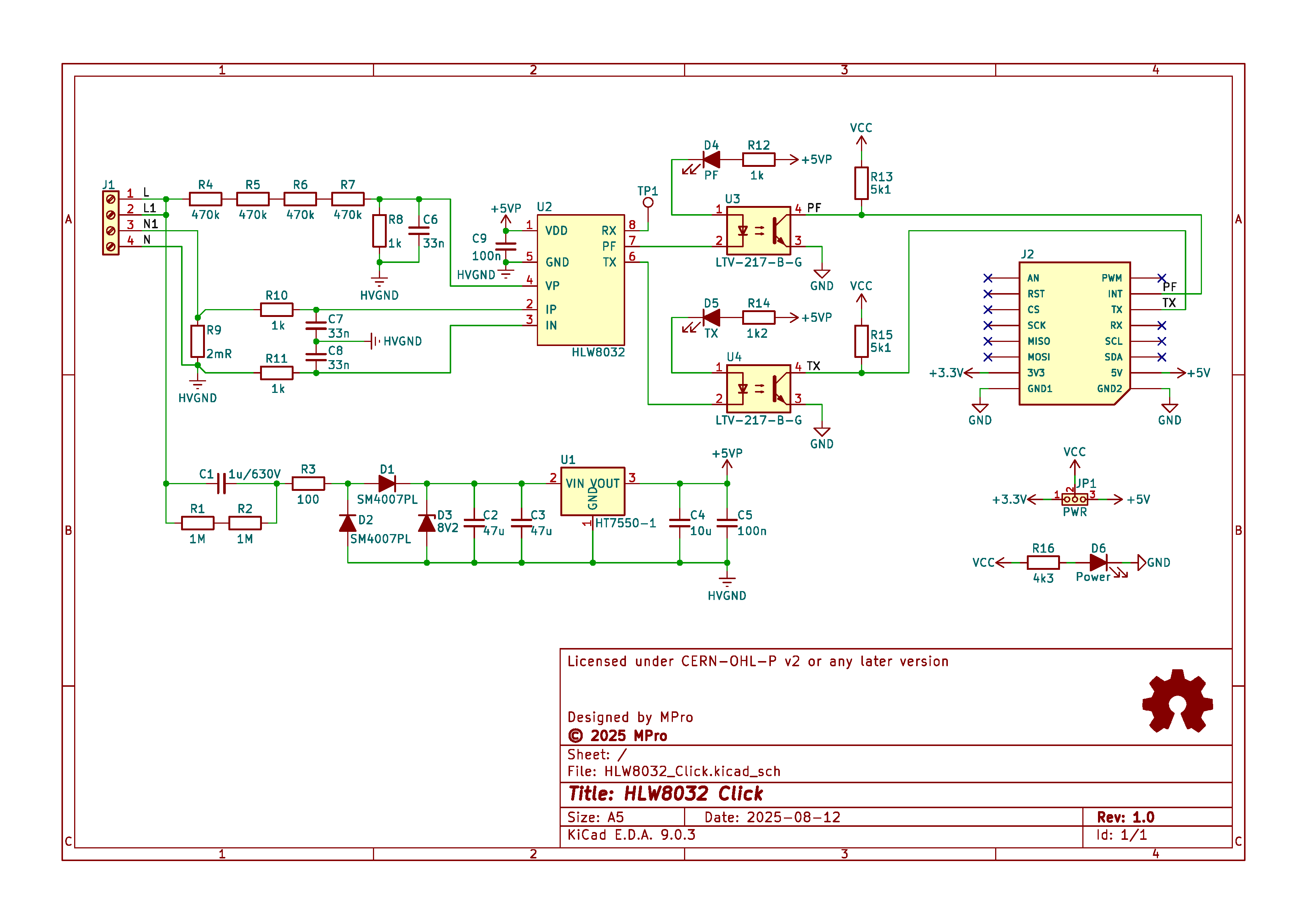
Schematic diagram

wiring diagram

Visual simulation of a transformerless power supply.

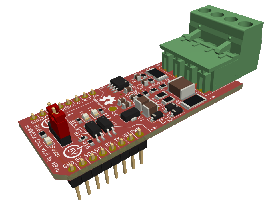
Module visualisation

(click on the image to see the 3D model)

LoRa Click

Assembly

Interactive BOM and placement

Production files

Production files can be found here.


Usage Guide

  • Connection:
    • Connect AC line to J1 (L/N) and load to L1/N1.
    • Plug into mikroBUS™ socket on a host board (e.g., MCU development kit).
    • Power via +5V/+3.3V pins.
  • Communication:
    • UART (TX/RX at 4800 baud, 8N1): Read 24-byte data frames for measurements.
    • PF Pin: Pulse output proportional to active electric energy.
  • Software:
    • Use MikroE libraries or custom code to parse HLW8032 registers.
    • Example: Voltage = (Register Value) * Calibration Factor.
  • Calibration: Adjust via software for shunt and divider ratios.
  • Safety: ** Handle high-voltage sections with care; ensure proper isolation **.

Reporting bugs

Create an issue on GitHub


License

Copyright © 2025 Michal Protasowicki

This project is released under CERN Open Hardware Licence Version 2 - Permissive.

License: CERN-OHL-P-2.0


Support

If You find my projects interesting and You wanted to support my work, You can give me a cup of coffee or a keg of beer :)

PayPal Direct     ko-fi     Coinbase

Parts

19
QtyValueFootprintReferences
32k2footprints:R_0805_2012MetricR1, R2, R3
1100nfootprints:C_0805_2012MetricC1
110ufootprints:C_0805_2012MetricC2
1A0footprints:PinHeader_1x03_P2.54mm_VerticalJP4
1A1footprints:PinHeader_1x03_P2.54mm_VerticalJP5
1A2footprints:PinHeader_1x03_P2.54mm_VerticalJP6
1AT24C256footprints:SO-8_3.9x4.9mm_P1.27mmU1
1I^{2}C EEPROM Click v${REVISION} by MProfootprints:mikroBUS_module_SJ1
1LOGOfootprints:Logo_Power_3V3REF1
1LOGOfootprints:Logo_Power_5VREF2
1Logo_Open_Hardware_Smallfootprints:OSHW-Logo2_7.3x6mm_SilkScreenLOGO1
1PWRfootprints:PinHeader_1x03_P2.54mm_VerticalJP1
1Powerfootprints:LED_0805_2012MetricD1
1SCLfootprints:SolderJumper-2_P1.3mm_Open_TrianglePad1.0x1.5mmJP2
1SDAfootprints:SolderJumper-2_P1.3mm_Open_TrianglePad1.0x1.5mmJP3
1WPfootprints:PinHeader_1x03_P2.54mm_VerticalJP7
1mikroBUS_logo_textfootprints:mikroBUS_logo_textREF4

More from michpro/mikroBUS

11
  • 2 layers25.4 × 57.2 mmOpenTherm Click, the printed circuit board in 3D

    OpenTherm Click

    michpro/mikroBUS

    Collection of add-on boards in mikroBUS™ standard

    58 parts5CERN-OHL-P-2.0
  • 2 layers96.5 × 81.3 mmBluePill base, the printed circuit board in 3D

    BluePill base

    michpro/mikroBUS

    Collection of add-on boards in mikroBUS™ standard

    48 parts5CERN-OHL-P-2.0
  • 2 layers25.4 × 57.2 mmHLW8032 Click, the printed circuit board in 3D

    HLW8032 Click

    michpro/mikroBUS

    Collection of add-on boards in mikroBUS™ standard

    45 parts5CERN-OHL-P-2.0
  • 2 layers25.4 × 42.9 mmLIN Click, the printed circuit board in 3D

    LIN Click

    michpro/mikroBUS

    Collection of add-on boards in mikroBUS™ standard

    34 parts5CERN-OHL-P-2.0
  • 2 layers25.4 × 57.2 mmLoRa Click, the printed circuit board in 3D

    LoRa Click

    michpro/mikroBUS

    Collection of add-on boards in mikroBUS™ standard

    26 parts5CERN-OHL-P-2.0
  • 2 layers25.4 × 42.9 mmCAN Click, the printed circuit board in 3D

    CAN Click

    michpro/mikroBUS

    Collection of add-on boards in mikroBUS™ standard

    25 parts5CERN-OHL-P-2.0
  • 2 layers25.4 × 57.2 mmSCT-013 UI Click, the printed circuit board in 3D

    SCT-013 UI Click

    michpro/mikroBUS

    Collection of add-on boards in mikroBUS™ standard

    25 parts5CERN-OHL-P-2.0
  • 2 layers68.6 × 53.3 mmArduino UNO click shield, the printed circuit board in 3D

    Arduino UNO click shield

    michpro/mikroBUS

    Collection of add-on boards in mikroBUS™ standard

    24 parts5CERN-OHL-P-2.0
  • 2 layers25.4 × 42.9 mmRS485 Click, the printed circuit board in 3D

    RS485 Click

    michpro/mikroBUS

    Collection of add-on boards in mikroBUS™ standard

    23 parts5CERN-OHL-P-2.0
  • 2 layers25.4 × 42.9 mmI2C 1-Wire Click, the printed circuit board in 3D

    I2C 1-Wire Click

    michpro/mikroBUS

    Collection of add-on boards in mikroBUS™ standard

    19 parts5CERN-OHL-P-2.0
  • 2 layers25.4 × 42.9 mmETH W5500 mini Click, the printed circuit board in 3D

    ETH W5500 mini Click

    michpro/mikroBUS

    Collection of add-on boards in mikroBUS™ standard

    8 parts5CERN-OHL-P-2.0

Similar boards

  • 2 layers70 × 65 mmTinyBas, the printed circuit board in 3D

    TinyBas

    Stan6314/TinyBasRV

    Small Tiny BASIC computer based on CH32V003

    38 parts36GPL-3.0
  • 2 layers33.7 × 36.6 mmHexyMicSMD, the printed circuit board in 3D

    HexyMicSMD

    AlexJMcIntyre/HexyHexyMic

    If you're here, there's a good chance you've picked up one of my HexyHexyMic Hexpansions. I hope I got the chance to say hello! If not, you can find me on Mastodon: @GlitchEngine@mastodon.social.

    11 parts5
  • 2 layers102.4 × 77.4 mmScheda PSE, the printed circuit board in 3D

    Scheda PSE

    Eduzyolo/PSE_project

    This is the official repo for the PSE project

    176 parts1
  • 4 layers40 × 36 mmMX IMU, the printed circuit board in 3D

    MX IMU

    lhaijun/MX_IMU

    55 parts1
  • 4 layers50 × 50 mmSTM32-DevBoard, the printed circuit board in 3D

    STM32-DevBoard

    s-grundner/STM32-DevBoard

    STM32 Breakout Board with various Sensors

    106 parts1
  • 2 layers99.1 × 99.1 mmFs6809sbc, the printed circuit board in 3D

    Fs6809sbc

    elekras/fs6809sbc

    A simple 6809 single board computer

    82 parts
  • 2 layers83 × 32 mmSchematics, the printed circuit board in 3D

    Schematics

    nicki419/Open-3-Step

    (WIP) Open-Source Circuit and code for custom built 120/240V 3-step (or n-step) light bulb dimmer working by turning off/on the light switch quickly to switch between brightness levels.

    24 partsApache-2.0
  • 2 layers90 × 36 mmAmbient, the printed circuit board in 3D

    Ambient

    RRomaNN/ambient-rgb-led

    This is a prototype of the LED backlight controller.

    51 parts

Questions

How big is the I2C EEPROM Click PCB?

It measures 25.4 × 28.6 mm and has 2 copper layers, 1.6 mm thick.

What parts does the I2C EEPROM Click use?

19 parts, built around the AT24C256N. The full list of its parts is on this page, with links to each part's symbol and footprint where PCBKit's library has them.

Where can I download the I2C EEPROM Click KiCad files?

From the michpro/mikroBUS repository on GitHub, at the commit this page was made from: the board is I2C_EEPROM_Click/I2C_EEPROM_Click.kicad_pcb and its schematic Arduino_UNO_click_shield/Arduino_UNO_click_shield.kicad_sch. PCBKit opens the board in the browser, with nothing to install.

Can I use the I2C EEPROM Click design in my own project?

Its repository publishes it under the CERN-OHL-P-2.0 licence: you may reuse it on that licence's terms (keep the author's notice, and for a copyleft licence share your changes alike).