
2 layers25.4 × 57.2 mm
OpenTherm Click
michpro/mikroBUS
Collection of add-on boards in mikroBUS™ standard
58 parts5CERN-OHL-P-2.0

 michpro/mikroBUS5
Collection of add-on boards in mikroBUS™ standard
Arduino UNO click shield is an open-source printed circuit board by michpro, from the michpro/mikroBUS repository on GitHub, published under the CERN-OHL-P-2.0 licence. It is a 2-layer board of 68.6 × 53.3 mm with 24 parts on 44 nets, routed with 304 tracks and 87 vias.
It is built around the PY32F030F18P6TU. Its parts include 4 resistors, 3 connectors, 2 capacitors and 1 IC.
The HLW8032 Click board is a compact energy metering module designed for integration with MikroElektronika's mikroBUS™ ecosystem. It utilizes the HLW8032 integrated circuit, a high-precision single-phase energy measurement chip capable of monitoring active power, voltage, current, and power factor. This board is suitable for applications in smart energy monitoring, IoT-based power management systems, and industrial automation where accurate real-time energy consumption data is required.
The board supports UART communication at 4800 baud for serial data output, providing registers for power, voltage, current, and energy accumulation.
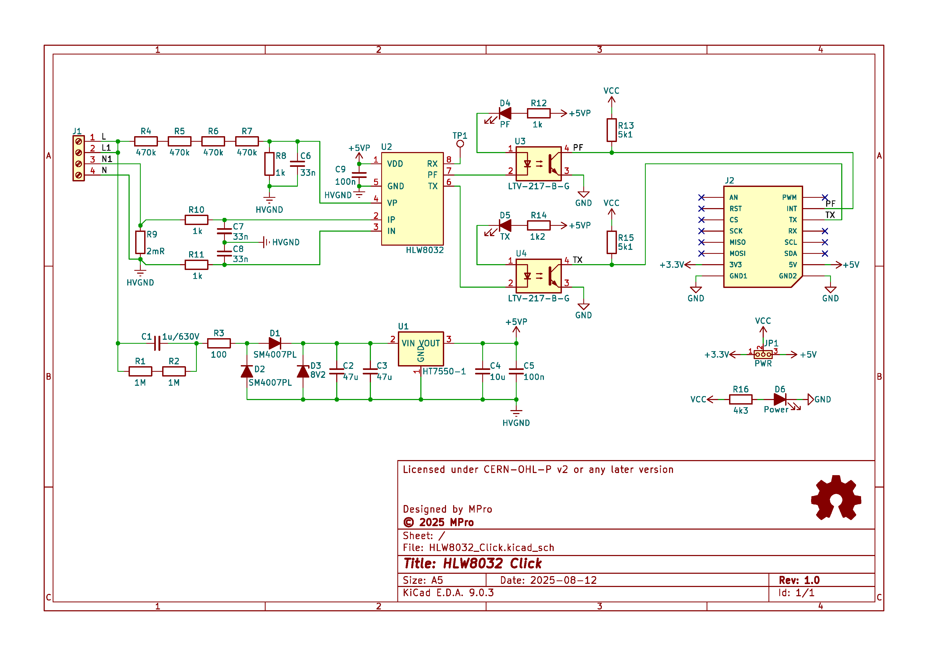
(click on the image to see the 3D model)
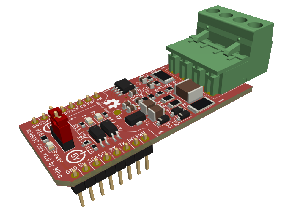
Production files can be found here.
Copyright © 2025 Michal Protasowicki
This project is released under CERN Open Hardware Licence Version 2 - Permissive.

If You find my projects interesting and You wanted to support my work, You can give me a cup of coffee or a keg of beer :)
| Qty | Value | Footprint | References |
|---|---|---|---|
| 2 | 10k | footprints:R_0805_2012Metric | R1, R2 |
| 2 | 2k2 | footprints:R_0805_2012Metric | R3, R4 |
| 2 | mikroBUS host connector | footprints:mikroBUS_host_connector | J1, J2 |
| 2 | ~ | footprints:TestPoint_Pad_D1.0mm | TP2, TP5 |
| 1 | 100n | footprints:C_0805_2012Metric | C1 |
| 1 | 10u | footprints:C_0805_2012Metric | C2 |
| 1 | Arduino UNO R3 Shield | footprints:Arduino_UNO_R3_WithMountingHoles_Profiled | A1 |
| 1 | GND | footprints:TestPoint_THTPad_D2.5mm_Drill1.2mm | TP1 |
| 1 | LOGO | footprints:Logo_Power_3V3 | LOGO3 |
| 1 | LOGO | footprints:Logo_Power_5V | LOGO2 |
| 1 | Logo_Open_Hardware_Small | footprints:OSHW-Logo2_7.3x6mm_SilkScreen | LOGO1 |
| 1 | PY32F030F18P6TU | Package_SO:TSSOP-20_4.4x6.5mm_P0.65mm | U1 |
| 1 | RX | footprints:TestPoint_Pad_D1.0mm | TP4 |
| 1 | RX | footprints:SolderJumper-2_P1.3mm_Open_RoundedPad1.0x1.5mm | JP5 |
| 1 | SCL | footprints:PinHeader_1x02_P2.54mm_Vertical | JP1 |
| 1 | SDA | footprints:PinHeader_1x02_P2.54mm_Vertical | JP2 |
| 1 | SWD | footprints:PinHeader_1x04_P2.54mm_Horizontal | J4 |
| 1 | TX | footprints:SolderJumper-2_P1.3mm_Open_RoundedPad1.0x1.5mm | JP4 |
| 1 | TX | footprints:TestPoint_Pad_D1.0mm | TP3 |
| 1 | VCC | footprints:SolderJumper-3_P1.3mm_Bridged12_RoundedPad1.0x1.5mm | JP3 |
michpro/mikroBUS
Collection of add-on boards in mikroBUS™ standard

michpro/mikroBUS
Collection of add-on boards in mikroBUS™ standard

michpro/mikroBUS
Collection of add-on boards in mikroBUS™ standard


michpro/mikroBUS
Collection of add-on boards in mikroBUS™ standard


michpro/mikroBUS
Collection of add-on boards in mikroBUS™ standard

michpro/mikroBUS
Collection of add-on boards in mikroBUS™ standard

michpro/mikroBUS
Collection of add-on boards in mikroBUS™ standard

llatva/pupill32
pu(rple)pill32 -- An indie evalboard for PY32F030F1xP6

dotnet/iot
This repo includes .NET Core implementations for various IoT boards, chips, displays and PCBs.

pascallanger/DIY-Multiprotocol-TX-Module
Multiprotocol TX Module (or MULTI-Module) is a 2.4GHz transmitter module which controls many different receivers and models.


rusefi/rusefi
rusefi - GPL internal combustion engine control unit

DraftShift/StealthChanger
Tool changing system for Vorons and other front mount printer motion systems, not just stealthburner.

VoronDesign/Voron-Hardware
Cool Hardware designed by the Voron Design group

hackclub/OnBoard
💡 Join 1,000 teenagers and make your first PCB with a $100 grant!
It measures 68.6 × 53.3 mm and has 2 copper layers, 1.6 mm thick.
24 parts, built around the PY32F030F18P6TU. The full list of its parts is on this page, with links to each part's symbol and footprint where PCBKit's library has them.
From the michpro/mikroBUS repository on GitHub, at the commit this page was made from: the board is Arduino_UNO_click_shield/Arduino_UNO_click_shield.kicad_pcb and its schematic Arduino_UNO_click_shield/Arduino_UNO_click_shield.kicad_sch. PCBKit opens the board in the browser, with nothing to install.
Its repository publishes it under the CERN-OHL-P-2.0 licence: you may reuse it on that licence's terms (keep the author's notice, and for a copyleft licence share your changes alike).