2 layers68 × 33 mm
MSPM0
mhered/KiCAD_udemy_course
My notes on the course "PCB design with KiCAD - updated for KiCAD 9" by Dr Peter Dalmaris in Udemy
51 parts2

 mhered/KiCAD_udemy_course2
My notes on the course "PCB design with KiCAD - updated for KiCAD 9" by Dr Peter Dalmaris in Udemy
Pico IoT thingy is an open-source printed circuit board by mhered, from the mhered/KiCAD_udemy_course repository on GitHub. It is a 4-layer board of 95 × 75 mm with 61 parts on 59 nets, routed with 361 tracks and 97 vias.
It is built around the THVD1406DRL, TSR 1-2450 and SHT31-DIS-F, with the TLV1117-33DCY, SS14 and BC817 among its other parts. Its parts include 20 resistors, 8 capacitors, 7 diodes, 7 connectors and 4 ICs. It belongs with the home automation and IoT boards and the RP2040 boards of this library.


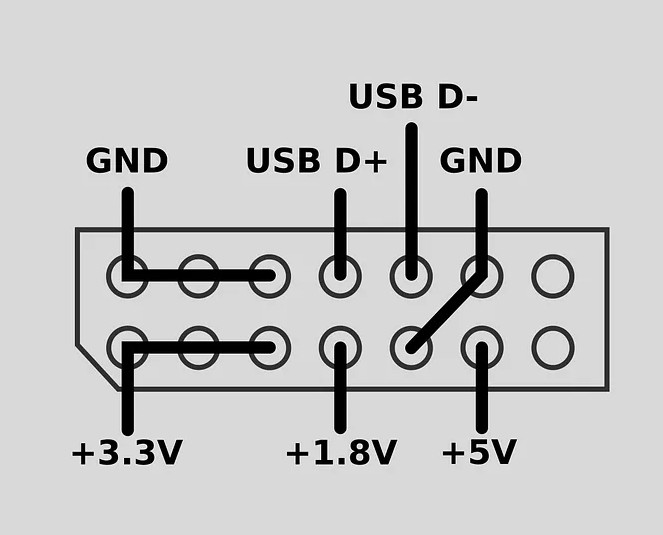
The original 2019 article: https://medium.com/robotics-weekends/how-to-turn-old-kinect-into-a-compact-usb-powered-rgbd-sensor-f23d58e10eb0 by Weekend Robotics describes tear own, splicing, and setting up the software with libfreenect for ROS1 Melodic
A facebook video by Weekend Robotics: https://www.facebook.com/watch/?v=615250869281835
Codrinidk in reddit r/robotics in 2023: https://www.reddit.com/r/robotics/comments/18xpa9s/finished_my_kinect_lite_project/ with comments on difficult steps
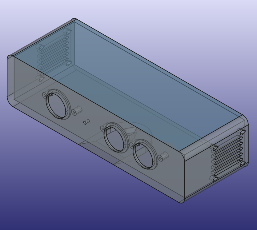
Case inspired by this STL from Printables: https://www.printables.com/model/229689-kinect-lite
Another case design in FreeCAD available in https://github.com/vojtapl/xbox360-kinect-lite
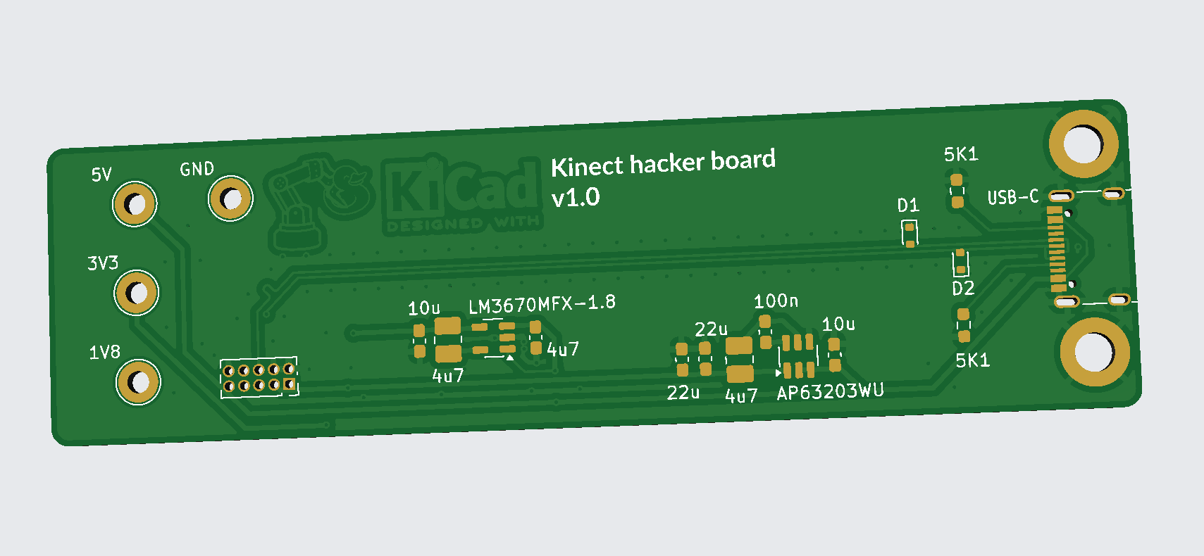
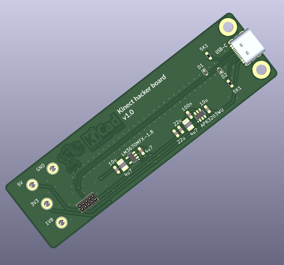
PCB inspired by this github repo: https://github.com/vojtapl/xbox360-kinect-lite

Kicad friendly PCB manufacturers: https://forum.kicad.info/t/kicad-friendly-pcb-manufacturers/47740
USB-C CAD model from https://www.3dcontentcentral.com/download-model.aspx?catalogid=171&id=1324314
$ kinect-3d-view
Waiting for sensor initialization...
Warning: Calibration file [kinect_calib.cfg] not found -> Using default params.
Could not find device sibling
Calling CKinect::initialize()...Exception in Kinect thread: ==== MRPT exception ====
Message:  Error opening Kinect sensor with index: 0
Location: /home/mhered/git/mrpt/libs/hwdrivers/src/CKinect.cpp:370: [void mrpt::hwdrivers::CKinect::open()
Call stack backtrace:
[0 ]     0x7f32408d9bcf
[1 ]     0x560d5876142c
[2 ]     0x7f323f4ecdb4
[3 ]     0x7f323f09caa4
[4 ]     0x7f323f129c6c

terminate called without an active exception
Aborted (core dumped)| Qty | Value | Footprint | References |
|---|---|---|---|
| 6 | 1KΩ | Resistor_SMD:R_1206_3216Metric_Pad1.30x1.75mm_HandSolder | R6, R7, R9, R11, R12, R13 |
| 6 | 4K7Ω | Resistor_SMD:R_1206_3216Metric_Pad1.30x1.75mm_HandSolder | R3, R4, R17, R18, R19, R20 |
| 4 | 10KΩ | Resistor_SMD:R_1206_3216Metric_Pad1.30x1.75mm_HandSolder | R1, R2, R8, R10 |
| 4 | MountingHole_Pad | MountingHole:MountingHole_3.2mm_M3_DIN965_Pad | H1, H2, H3, H4 |
| 3 | 100u | Capacitor_SMD:C_1206_3216Metric_Pad1.33x1.80mm_HandSolder | C1, C4, C7 |
| 2 | 10Ω | Resistor_SMD:R_1206_3216Metric_Pad1.30x1.75mm_HandSolder | R15, R16 |
| 2 | 22u/16V | Capacitor_SMD:C_1206_3216Metric_Pad1.33x1.80mm_HandSolder | C5, C6 |
| 2 | SS14 | Diode_SMD:D_SMA | D2, D4 |
| 2 | SW_SPST | Button_Switch_SMD:SW_Tactile_SPST_NO_Straight_CK_PTS636Sx25SMTRLFS | SW1, SW2 |
| 1 | 0Ω | Resistor_SMD:R_1206_3216Metric_Pad1.30x1.75mm_HandSolder | R5 |
| 1 | 100n | Capacitor_SMD:C_1206_3216Metric_Pad1.33x1.80mm_HandSolder | C8 |
| 1 | 10u/16V | Capacitor_SMD:C_1206_3216Metric_Pad1.33x1.80mm_HandSolder | C3 |
| 1 | 120Ω | Resistor_SMD:R_1206_3216Metric_Pad1.30x1.75mm_HandSolder | R14 |
| 1 | 1A | MH_MF-SM100:MFSM1002 | F1 |
| 1 | 2u2/50V | Capacitor_SMD:C_1206_3216Metric_Pad1.33x1.80mm_HandSolder | C2 |
| 1 | BC817 | Package_TO_SOT_SMD:SOT-23 | Q1 |
| 1 | Barrel_Jack_Switch | Connector_BarrelJack:BarrelJack_GCT_DCJ200-10-A_Horizontal | J1 |
| 1 | Conn_01x02 | Connector_PinHeader_2.54mm:PinHeader_1x02_P2.54mm_Vertical | J7 |
| 1 | Conn_01x03 | Connector_PinHeader_2.54mm:PinHeader_1x03_P2.54mm_Vertical | J3 |
| 1 | Conn_02x05_Odd_Even | Connector_PinHeader_2.54mm:PinHeader_2x05_P2.54mm_Vertical | J6 |
| 1 | GREEN | LED_SMD:LED_1206_3216Metric_Pad1.42x1.75mm_HandSolder | D3 |
| 1 | KiCad-Logo2_5mm_SilkScreen | Symbol:KiCad-Logo2_5mm_SilkScreen | KICAD_LOGO |
| 1 | LED_RGBA | LED_SMD:LED_RGB_1210 | D8 |
| 1 | LOGO | MH_logos:robot_duckie_logo_12mm | G*** |
| 1 | MH_Symbol_HighVoltage_Triangle_8x7mm_Silkscreen | MH_logos:MH_Symbol_HighVoltage_Triangle_8x7mm_Silkscreen | HIGHVOLT_LOGO |
| 1 | QWIIC | Connector_JST:JST_SH_SM04B-SRSS-TB_1x04-1MP_P1.00mm_Horizontal | J2 |
| 1 | RT314A05 | Relay_THT:Relay_SPDT_Schrack-RT1-16A-FormC_RM5mm | K1 |
| 1 | RaspberryPi_Pico_W | Module:RaspberryPi_Pico_W_SMD_HandSolder | A1 |
| 1 | SHT31-DIS | Sensor_Humidity:Sensirion_DFN-8-1EP_2.5x2.5mm_P0.5mm_EP1.1x1.7mm | U2 |
| 1 | SM712_SOT23 | Package_TO_SOT_SMD:SOT-23 | D7 |
| 1 | SMAJ24A | MH_SMAJ24A:DIOM5127X229N | D1 |
| 1 | SW_DIP_x04 | MH_DIPSWITCH:2194MST | SW3 |
| 1 | Screw_Terminal_01x03 | TerminalBlock:TerminalBlock_MaiXu_MX126-5.0-03P_1x03_P5.00mm | J4 |
| 1 | Screw_Terminal_01x04 | TerminalBlock:TerminalBlock_MaiXu_MX126-5.0-04P_1x04_P5.00mm | J5 |
| 1 | SolderJumper_2_Open | Jumper:SolderJumper-2_P1.3mm_Open_RoundedPad1.0x1.5mm | JP1 |
| 1 | THVD1406DR | Package_SO:SOIC-8_3.9x4.9mm_P1.27mm | IC1 |
| 1 | TLV1117-33 | Package_TO_SOT_SMD:SOT-223-3_TabPin2 | U3 |
| 1 | TSR_1-2450 | Converter_DCDC:Converter_DCDC_TRACO_TSR-1_THT | U1 |
| 1 | YELLOW | LED_SMD:LED_1206_3216Metric_Pad1.42x1.75mm_HandSolder | D5 |
mhered/KiCAD_udemy_course
My notes on the course "PCB design with KiCAD - updated for KiCAD 9" by Dr Peter Dalmaris in Udemy

mhered/KiCAD_udemy_course
My notes on the course "PCB design with KiCAD - updated for KiCAD 9" by Dr Peter Dalmaris in Udemy

mhered/KiCAD_udemy_course
My notes on the course "PCB design with KiCAD - updated for KiCAD 9" by Dr Peter Dalmaris in Udemy

mhered/KiCAD_udemy_course
My notes on the course "PCB design with KiCAD - updated for KiCAD 9" by Dr Peter Dalmaris in Udemy

mhered/KiCAD_udemy_course
My notes on the course "PCB design with KiCAD - updated for KiCAD 9" by Dr Peter Dalmaris in Udemy

mhered/KiCAD_udemy_course
My notes on the course "PCB design with KiCAD - updated for KiCAD 9" by Dr Peter Dalmaris in Udemy

Itachi-infinito/Raspberry-Pico-IoT-4-Layer-PCB
Raspberry Pi Pico IoT device on 4-layer PCB with sensors, KiCad schematics, PCB layout and 3D visualization.

Ayan-nova/Design-of-a-Raspberry-PICO-Iot-Device-on-4-Layer-PCB-Design-With-Sensor-And-More
Design a Raspberry Pi Pico W-based Industrial IoT Gateway and Edge Controller using Kicad software.


PragyanSenDeka/RaspberryPiPicoBasedHomeAutomationPCB
Home automation node based on Raspberry Pi Pico W with WiFi and RS485/MODBUS. Features DIP-switch addressing, SHT31 temperature/humidity sensor, QWIIC I2C, RGB LED, buttons, SPI expansion, and a 230V 16A relay.

Habib-creater/ESP32-IoT-Monitoring-Control-Board
4-layer ESP32-based IoT monitoring and control board with environmental sensing, relay control, USB-C, and Qwiic expansion.


Tanmayeers/Projects
Specifications: 1. Operting Voltage: 9V 2. Operating Current: 200mA 3. Output Voltage Swing: 6.5V 4. 3dB - Bandwidth: 100 ± 10 Hz 5. Noise: 5.406mVrms

jayatharshan12-design/ESP32-Custom-Development-Board-PCB-Design
It measures 95 × 75 mm and has 4 copper layers, 1.6 mm thick.
61 parts, built around the THVD1406DRL, TSR 1-2450, SHT31-DIS-F and TLV1117-33DCY. The full list of its parts is on this page, with links to each part's symbol and footprint where PCBKit's library has them.
From the mhered/KiCAD_udemy_course repository on GitHub, at the commit this page was made from: the board is projects/06_pico_IoT_thingy/pico_IoT_thingy.kicad_pcb and its schematic projects/01_LED_torch/LED_torch.kicad_sch. PCBKit opens the board in the browser, with nothing to install.
Its repository states no licence, so its author keeps all rights: ask mhered before reusing the design.