6 layers160 × 100 mm

 mhardeman/matt-poe-prototype5
PoE Powered Device (PD) Prototype Schematic & PCB design in KiCad for 12V & 5V output rails
Matt poe prototype is an open-source printed circuit board by mhardeman, from the mhardeman/matt-poe-prototype repository on GitHub. It is a 2-layer board of 123 × 91.6 mm with 56 parts on 41 nets, routed with 124 tracks and 91 vias.
It is built around the PZ200V-11-02P, GR442QR73D102KW01L and ABS10, with the EP475SG-10, SBRT20U60SP5-7D and SMAJ58A among its other parts. Its parts include 21 capacitors, 10 resistors, 4 diodes, 2 ICs and 2 inductors. It belongs with the interfaces and adapters boards of this library.


This is a KiCad design containing a schematic & PCB layout for a prototype PoE (Power over Ethernet) PD (Powered Device).
It provides for output isolation between the PoE delivery and the output power rails. It provides for both 12V and 5V output rails, with a common ground for those two rails.
This is a prototype. I'm happy to accept issues with questions or suggestions for improvement, and would very happily review any pull requests that come in.
Apparently some one(s) at PCBWay saw this Github project or my post(s) about it on Reddit, because a representative from PCBWay reached out to me and offered to sponsor a run of these boards for free and even let me get a free solder stencil with the boards, all for the simple ask that I provide an honest review of the sponsored boards & stencil. My review is: they look & feel great, and they function fantastically. I'll be posting more -- including an assembly and testing video -- in the coming days. In the mean time, check out the photos of the PCBWay boards All told, PCBWay let me put together a purchase of these boards, the stencil, and some premium options, and shipping, all without cost to me. It's wonderful to see a company serving both hobbyists and industry ALSO materially contribute! I'm grateful.
This design utilizes the 3Peak TPE15017 and/or Monolithic Power Systems MP8017 -- they're largely interchangeable in this design, though tolerances on the 3Peak seem to be favorable, which can improve your efficiency. This tiny IC handles the PoE power detection and classification and provides an active-clamp flyback controller with integrated low-side & clamp MOSFETs. This part, in conjunction with an appropriate transformer provides a 12V output rail, which is further routed in this design to an inexpensive buck converter to provide for a 5V output rail.
In my testing up to this point, this design easily provides at least 10W of usable power out the 5V rail. I've had it pulling 5V/2A on my DC test load continuously for several days.
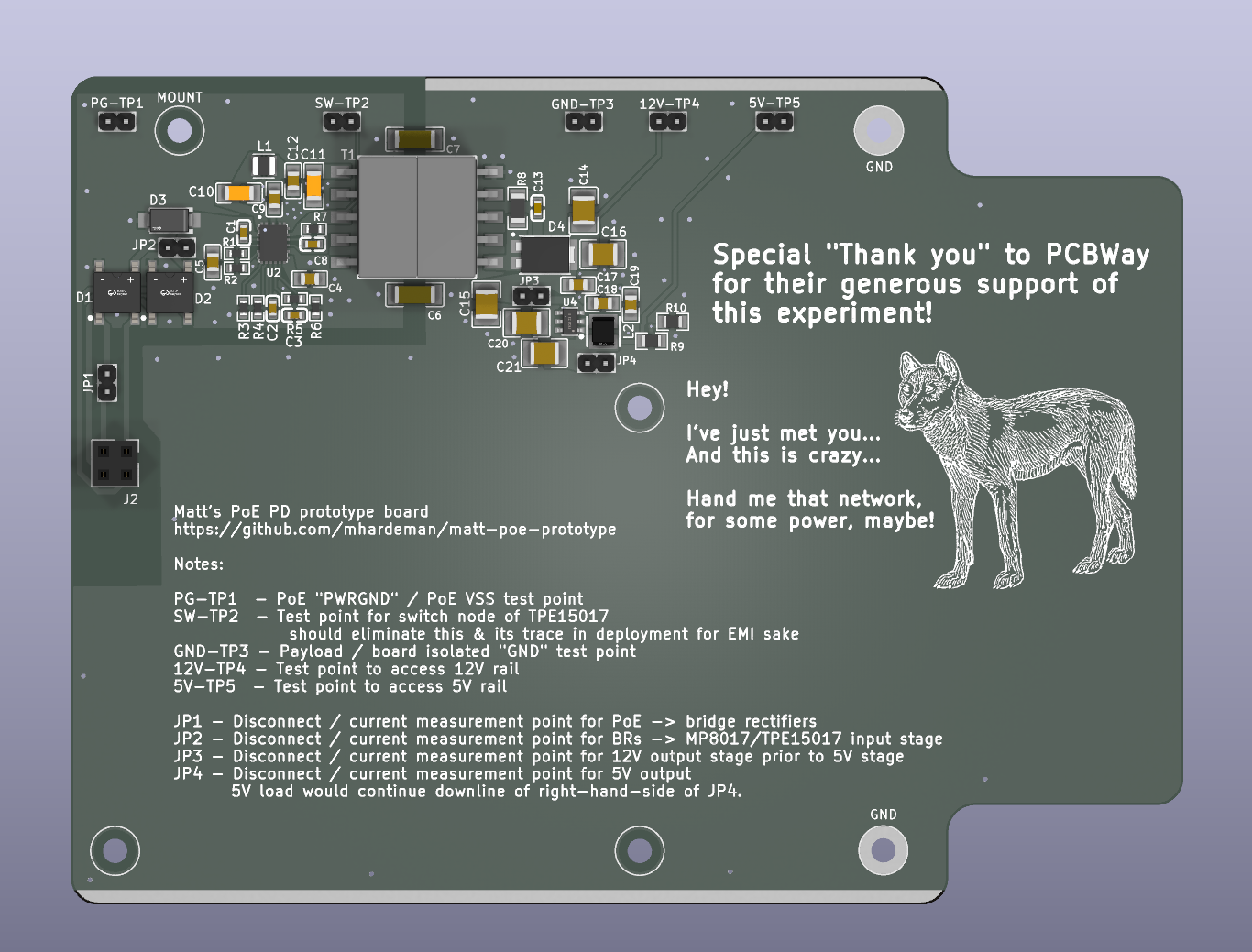
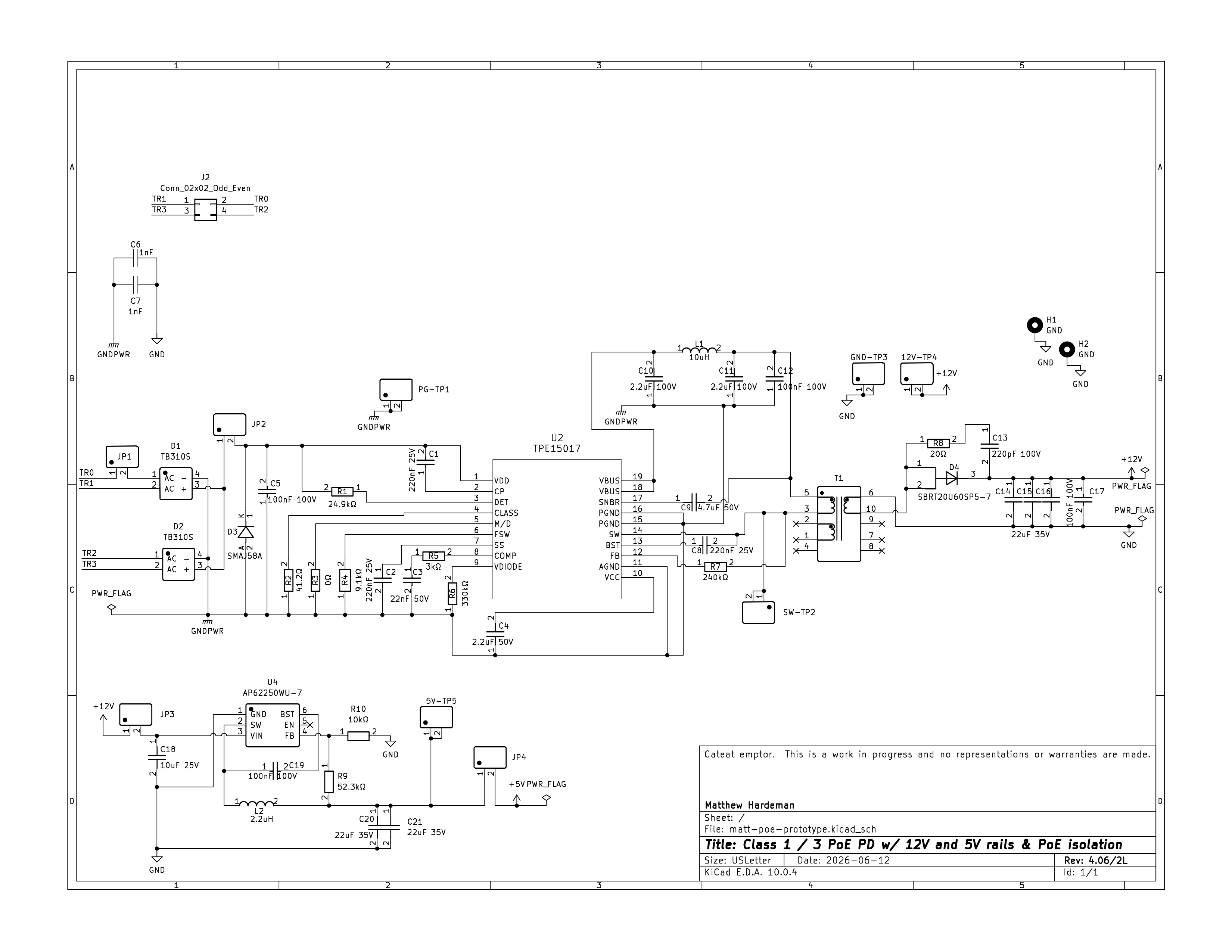
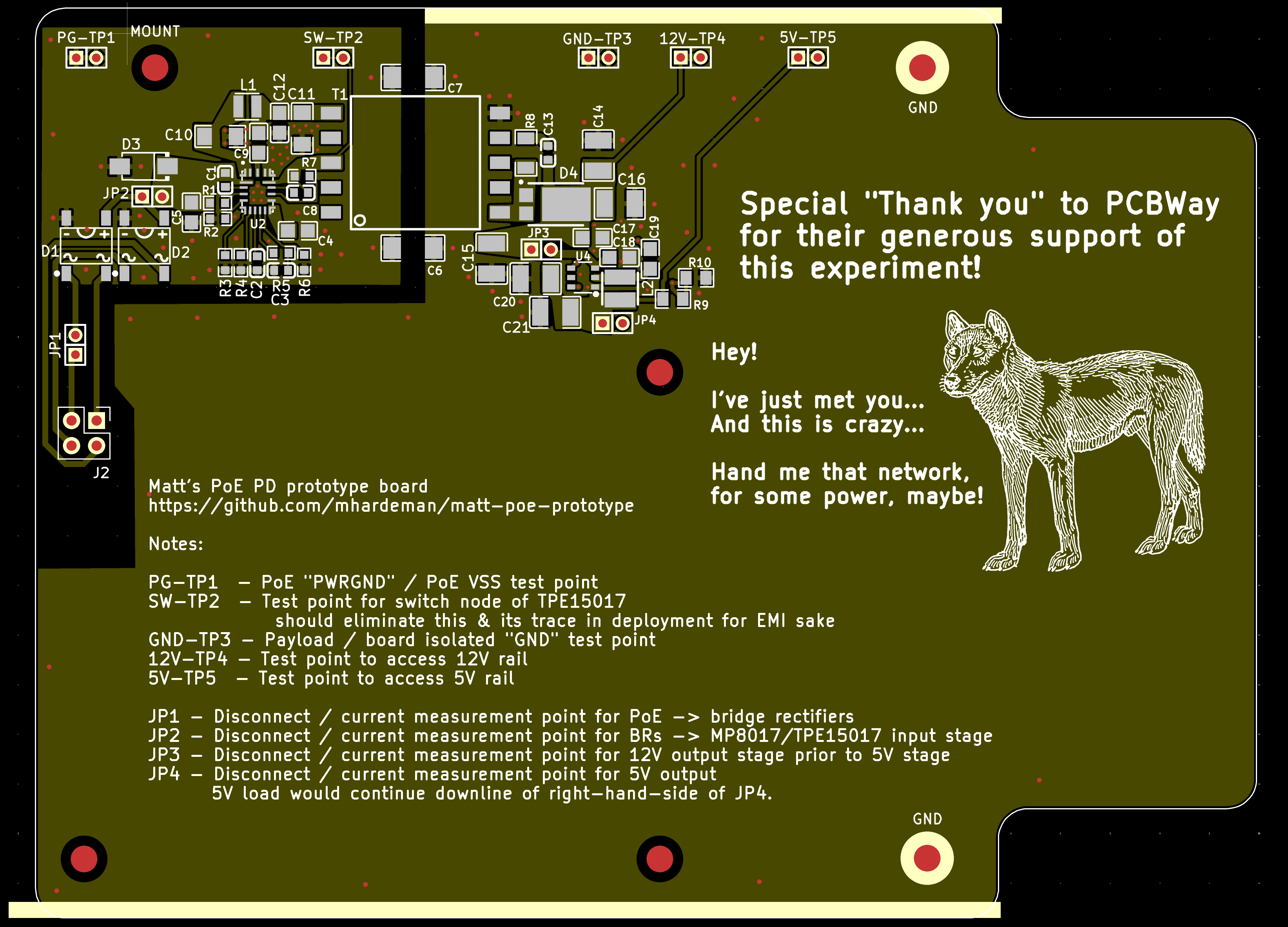
| Qty | Value | Footprint | References |
|---|---|---|---|
| 9 | PZ200V-11-02P | JLCImport:PZ200V-11-02P | 5V-TP5, 12V-TP4, GND-TP3, JP1, JP2, JP3, JP4, PG-TP1, SW-TP2 |
| 5 | 22uF 35V | JLCImport:C_1210_C778721 | C14, C15, C16, C20, C21 |
| 4 | 100nF 100V | JLCImport:C_0805_C28233 | C5, C12, C17, C19 |
| 4 | MountingHole_2.7mm_M2.5 | MountingHole:MountingHole_2.7mm_M2.5 | MH2, MH3, MH4, MOUNT |
| 3 | 220nF 25V | JLCImport:CL10B224KA8NNNC | C1, C2, C8 |
| 2 | 1nF | jlcpcbfootprint:C1808 | C6, C7 |
| 2 | 2.2uF 100V | JLCImport:C_1206_C170101 | C10, C11 |
| 2 | GND | MountingHole:MountingHole_2.7mm_M2.5_Pad_TopBottom | H1, H2 |
| 2 | TB310S | JLCImport:ABS_TB310S | D1, D2 |
| 1 | 0Ω | JLCImport:R_0603_C21189 | R3 |
| 1 | 10kΩ | JLCImport:R_0805_C17414 | R10 |
| 1 | 10uF 25V | JLCImport:GRM21BZ71E106KE15L | C18 |
| 1 | 10uH | JLCImport:DFE252012F-100M_P2 | L1 |
| 1 | 2.2uF 50V | JLCImport:C_0805_C377773 | C4 |
| 1 | 2.2uH | JLCImport:L_1210_C18724399 | L2 |
| 1 | 20Ω | JLCImport:R_1206_C17903 | R8 |
| 1 | 220pF 100V | JLCImport:GCM1885C2A221JA16D | C13 |
| 1 | 22nF 50V | JLCImport:C_0603_C21122 | C3 |
| 1 | 24.9kΩ | JLCImport:R_0603_C25962 | R1 |
| 1 | 240kΩ | JLCImport:R_0603_C4197 | R7 |
| 1 | 330kΩ | JLCImport:0603WAF3303T5E | R6 |
| 1 | 3kΩ | JLCImport:R_0603_C4211 | R5 |
| 1 | 4.7uF 50V | JLCImport:C_0805_C437557 | C9 |
| 1 | 41.2Ω | JLCImport:R_0603_C246850 | R2 |
| 1 | 52.3kΩ | JLCImport:R_0805_C17740 | R9 |
| 1 | 9.1kΩ | JLCImport:FRC0603J912_TS | R4 |
| 1 | AP62250WU-7 | JLCImport:AP62250WU-7 | U4 |
| 1 | Conn_02x02_Odd_Even | Connector_PinSocket_2.54mm:PinSocket_2x02_P2.54mm_Vertical | J2 |
| 1 | EP475SG-10 | JLCImport:XFMR_EP13_EP475SG-10 | T1 |
| 1 | SBRT20U60SP5-7 | JLCImport:SBRT20U60SP5-7 | D4 |
| 1 | SMAJ58A | JLCImport:SMAJ58A_C19077554 | D3 |
| 1 | TPE15017 | MPS:QFN-19_MP8017_MNP | U2 |
It measures 123 × 91.6 mm and has 2 copper layers, 1.6 mm thick.
56 parts, built around the PZ200V-11-02P, GR442QR73D102KW01L, ABS10 and EP475SG-10. The full list of its parts is on this page, with links to each part's symbol and footprint where PCBKit's library has them.
From the mhardeman/matt-poe-prototype repository on GitHub, at the commit this page was made from: the board is matt-poe-prototype.kicad_pcb and its schematic matt-poe-prototype.kicad_sch. PCBKit opens the board in the browser, with nothing to install.
Its repository states no licence, so its author keeps all rights: ask mhardeman before reusing the design.

stanford-ssi/Hummingbird-KiCad
Apr 7, 2025 (Koichi K.): Created the PCB layout. Next steps: figure out power and traces.

oats-center/avena-rs
Avena On The Road: Bringing pavement health data to your fingertips


skndungu/220-110VAC-to-5V-3A-Adapter
This repo contains a PCB design for a 220/110VAC to 5V 3A adapter for your 5V appliances and mobile phone for fast charging and powering


ISLKey/islkey
ISLKey access-control platform — ESP32 firmware, Electron flasher, Flutter app, KiCad schematic (ISL Technologies)