2 layers65 × 71.5 mm

 MG-5/vfd-clock-hardware1
Hardware for controlling six VFD IV-17 tubes as clock (HH:MM:SS)
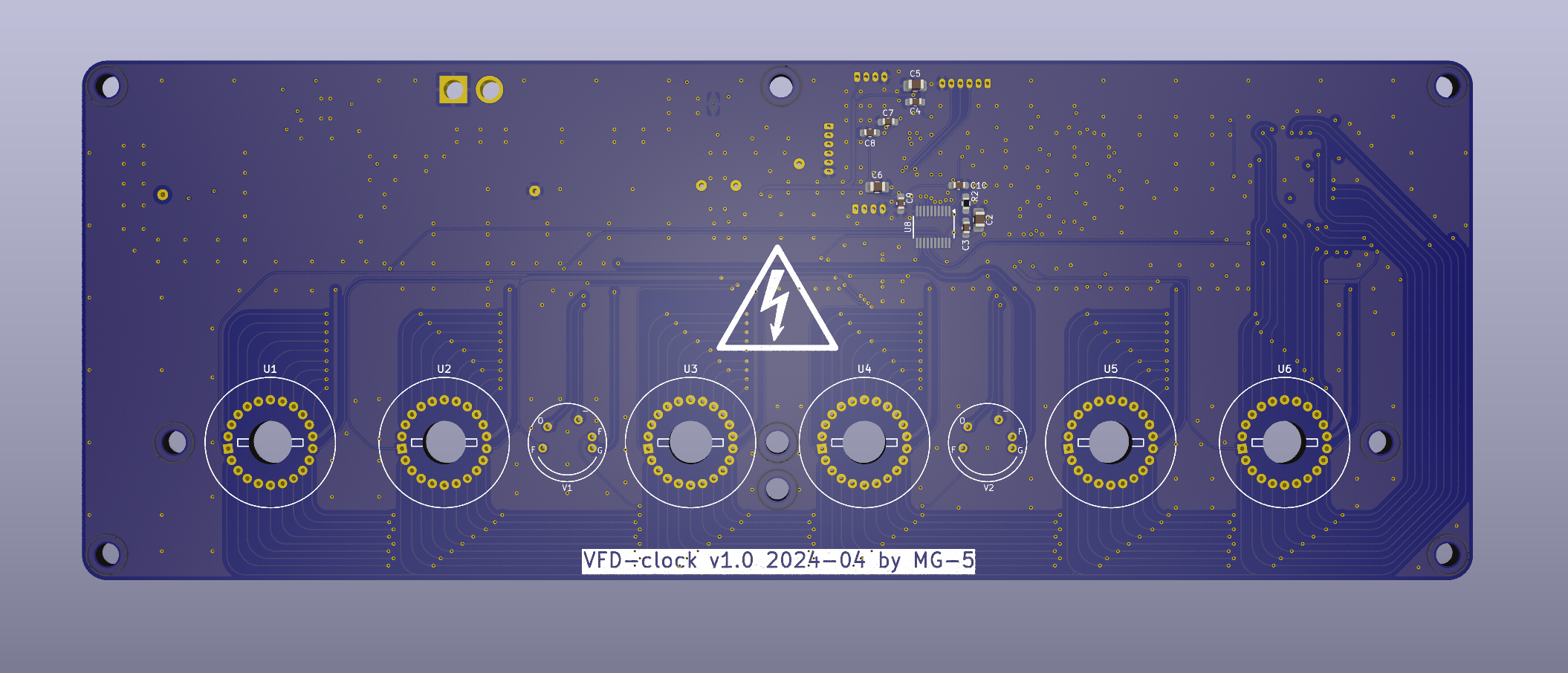
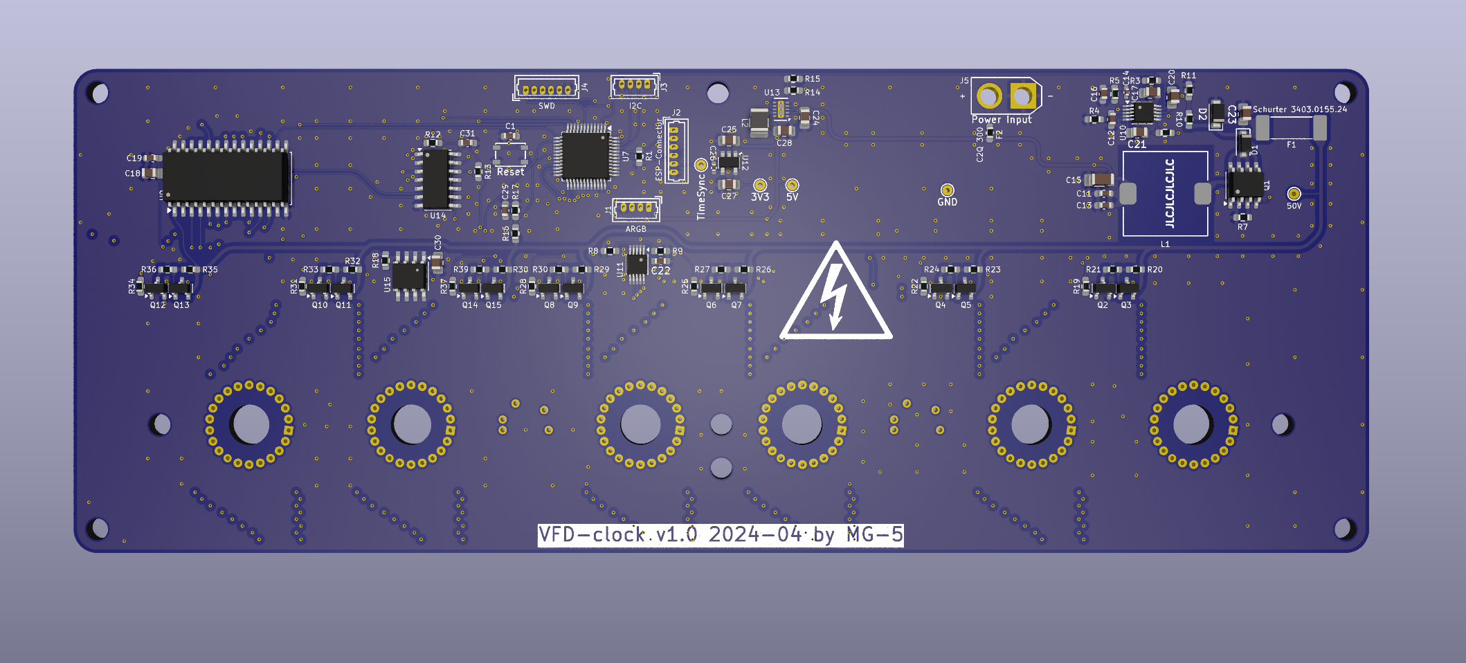
Vfd clock is an open-source printed circuit board by MG-5, from the MG-5/vfd-clock-hardware repository on GitHub, published under the MIT licence. It is a 4-layer board of 192 × 71.8 mm with 130 parts on 138 nets, routed with 1,233 tracks and 668 vias.
It is built around the SN74HCS541DGS, HV5812P-G and LT3757AEMSE#PBF, with the MIC4801YM, MIC4811YMM and TPS62175DQC among its other parts. Its parts include 39 resistors, 31 capacitors, 15 ICs, 15 transistors and 5 connectors. It belongs with the lEDs and displays boards and the STM32 boards of this library.


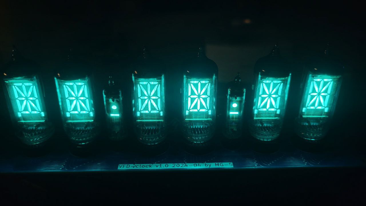
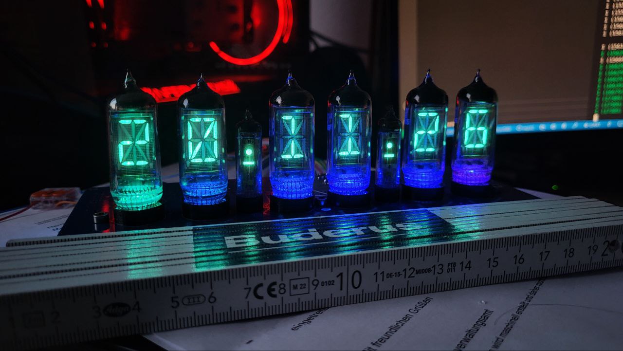
Hardware for controlling six VFD IV-17 and two VFD IV-1 tubes as clock (HH:MM:SS)
| Qty | Value | Footprint | References |
|---|---|---|---|
| 12 | 10k | Resistor_SMD:R_0603_1608Metric_Pad0.98x0.95mm_HandSolder | R1, R2, R3, R9, R17, R19, R22, R25, R28, R31, R34, R37 |
| 10 | 100n | Capacitor_SMD:C_0603_1608Metric_Pad1.08x0.95mm_HandSolder | C1, C3, C4, C7, C8, C9, C10, C19, C29, C31 |
| 9 | MountingHole_Pad | MountingHole:MountingHole_3.2mm_M3_ISO14580 | H1, H2, H3, H4, H5, H6, H7, H8, H9 |
| 7 | 100k | Resistor_SMD:R_0603_1608Metric_Pad0.98x0.95mm_HandSolder | R21, R24, R27, R30, R33, R36, R39 |
| 7 | 220k | Resistor_SMD:R_0603_1608Metric_Pad0.98x0.95mm_HandSolder | R20, R23, R26, R29, R32, R35, R38 |
| 7 | BC846 | Package_TO_SOT_SMD:SOT-23 | Q2, Q4, Q6, Q8, Q10, Q12, Q14 |
| 7 | BC856 | Package_TO_SOT_SMD:SOT-23 | Q3, Q5, Q7, Q9, Q11, Q13, Q15 |
| 6 | IV-17 | extraFootprints:IV-17 | U1, U2, U3, U4, U5, U6 |
| 5 | 1u | Capacitor_SMD:C_0805_2012Metric_Pad1.18x1.45mm_HandSolder | C2, C5, C18, C25, C27 |
| 2 | 100n 35V | Capacitor_SMD:C_0603_1608Metric_Pad1.08x0.95mm_HandSolder | C11, C13 |
| 2 | 2k2 | Resistor_SMD:R_0603_1608Metric_Pad0.98x0.95mm_HandSolder | R12, R13 |
| 2 | ~ | mynixies:mynixies-IV-1 | V1, V2 |
| 1 | 10n | Capacitor_SMD:C_0805_2012Metric_Pad1.18x1.45mm_HandSolder | C21 |
| 1 | 10u | Capacitor_SMD:C_0805_2012Metric_Pad1.18x1.45mm_HandSolder | C6 |
| 1 | 10u | Inductor_SMD:L_1210_3225Metric_Pad1.42x2.65mm_HandSolder | L2 |
| 1 | 10u 16V | Capacitor_SMD:C_0805_2012Metric_Pad1.18x1.45mm_HandSolder | C20 |
| 1 | 10u 35V | Capacitor_SMD:C_1206_3216Metric_Pad1.33x1.80mm_HandSolder | C15 |
| 1 | 11k | Resistor_SMD:R_0603_1608Metric_Pad0.98x0.95mm_HandSolder | R11 |
| 1 | 120k | Resistor_SMD:R_0603_1608Metric_Pad0.98x0.95mm_HandSolder | R14 |
| 1 | 180k | Resistor_SMD:R_0603_1608Metric_Pad0.98x0.95mm_HandSolder | R16 |
| 1 | 18k | Resistor_SMD:R_0603_1608Metric_Pad0.98x0.95mm_HandSolder | R8 |
| 1 | 1n | Capacitor_SMD:C_0603_1608Metric_Pad1.08x0.95mm_HandSolder | C16 |
| 1 | 22 | Resistor_SMD:R_0603_1608Metric_Pad0.98x0.95mm_HandSolder | R6 |
| 1 | 220n 35V | Capacitor_SMD:C_0805_2012Metric_Pad1.18x1.45mm_HandSolder | C17 |
| 1 | 22k | Resistor_SMD:R_0603_1608Metric_Pad0.98x0.95mm_HandSolder | R15 |
| 1 | 22p | Capacitor_SMD:C_0402_1005Metric_Pad0.74x0.62mm_HandSolder | C14 |
| 1 | 22u | Capacitor_SMD:C_0805_2012Metric_Pad1.18x1.45mm_HandSolder | C28 |
| 1 | 24k3 | Resistor_SMD:R_0603_1608Metric_Pad0.98x0.95mm_HandSolder | R4 |
| 1 | 2u2 35V | Capacitor_SMD:C_0805_2012Metric_Pad1.18x1.45mm_HandSolder | C24 |
| 1 | 330k | Resistor_SMD:R_0603_1608Metric_Pad0.98x0.95mm_HandSolder | R10 |
| 1 | 360m | Resistor_SMD:R_0603_1608Metric_Pad0.98x0.95mm_HandSolder | R7 |
| 1 | 3V3 | TestPoint:TestPoint_THTPad_D1.5mm_Drill0.7mm | TP2 |
| 1 | 470n 60V | Capacitor_SMD:C_0805_2012Metric_Pad1.18x1.45mm_HandSolder | C23 |
| 1 | 470p | Capacitor_SMD:C_0402_1005Metric_Pad0.74x0.62mm_HandSolder | C26 |
| 1 | 470u (NS12555T471MN) | extraFootprints:Taiyo Yuden NS 12.5mmx12.5mm | L1 |
| 1 | 47n | Capacitor_SMD:C_0603_1608Metric_Pad1.08x0.95mm_HandSolder | C12 |
| 1 | 4u7 | Capacitor_SMD:C_0603_1608Metric_Pad1.08x0.95mm_HandSolder | C22 |
| 1 | 4u7 | Capacitor_SMD:C_0805_2012Metric_Pad1.18x1.45mm_HandSolder | C30 |
| 1 | 50V | TestPoint:TestPoint_THTPad_D1.5mm_Drill0.7mm | TP4 |
| 1 | 56k | Resistor_SMD:R_0603_1608Metric_Pad0.98x0.95mm_HandSolder | R5 |
| 1 | 5V | TestPoint:TestPoint_THTPad_D1.5mm_Drill0.7mm | TP3 |
| 1 | 93k1 | Resistor_SMD:R_0603_1608Metric_Pad0.98x0.95mm_HandSolder | R18 |
| 1 | ARGB | Connector_Molex:Molex_PicoBlade_53047-0410_1x04_P1.25mm_Vertical | J1 |
| 1 | C2Q 300 | Fuse:Fuse_0603_1608Metric_Pad1.05x0.95mm_HandSolder | F2 |
| 1 | ESP-Connector | Connector_Molex:Molex_PicoBlade_53047-0610_1x06_P1.25mm_Vertical | J2 |
| 1 | FDS2734 | Package_SO:SOIC-8_3.9x4.9mm_P1.27mm | Q1 |
| 1 | GND | TestPoint:TestPoint_THTPad_D1.5mm_Drill0.7mm | TP1 |
| 1 | HS1FFL | Diode_SMD:D_SOD-123F | D1 |
| 1 | HV5812 | Package_SO:SOIC-28W_7.5x17.9mm_P1.27mm | U9 |
| 1 | I2C | Connector_Molex:Molex_PicoBlade_53047-0410_1x04_P1.25mm_Vertical | J3 |
| 1 | LT3757AEMSE | Package_SO:MSOP-10-1EP_3x3mm_P0.5mm_EP1.68x1.88mm | U10 |
| 1 | MIC4801 | Package_SO:PowerIntegrations_SO-8 | U15 |
| 1 | MIC4811 | Package_SO:MSOP-10_3x3mm_P0.5mm | U11 |
| 1 | PTS815 | Button_Switch_SMD:SW_SPST_PTS810 | SW1 |
| 1 | Power Input | Connector_AMASS:AMASS_XT30U-M_1x02_P5.0mm_Vertical | J5 |
| 1 | SN74HCS08 | Package_SO:SOIC-14_3.9x8.7mm_P1.27mm | U14 |
| 1 | SN74HCS541 | extraFootprints:VSSOP-20_5.1x3mm_P0.5mm | U8 |
| 1 | STM32F103CBTx | Package_QFP:LQFP-48_7x7mm_P0.5mm | U7 |
| 1 | SWD | Connector_Molex:Molex_PicoBlade_53047-0610_1x06_P1.25mm_Vertical | J4 |
| 1 | Schurter 3403.0155.24 | Fuse:Fuse_Schurter_UMT250 | F1 |
| 1 | TC1185 | Package_TO_SOT_SMD:SOT-23-5 | U12 |
| 1 | TPS62175DQC | Package_SON:WSON-10-1EP_2x3mm_P0.5mm_EP0.84x2.4mm_ThermalVias | U13 |
| 1 | TVS TPSMB62A | Diode_SMD:D_SMF | D2 |
| 1 | TimeSync | TestPoint:TestPoint_THTPad_D1.5mm_Drill0.7mm | TP5 |
The 128 most common of 130 parts.
It measures 192 × 71.8 mm and has 4 copper layers, 1.6 mm thick.
130 parts, built around the SN74HCS541DGS, HV5812P-G, LT3757AEMSE#PBF and MIC4801YM. The full list of its parts is on this page, with links to each part's symbol and footprint where PCBKit's library has them.
From the MG-5/vfd-clock-hardware repository on GitHub, at the commit this page was made from: the board is vfd-clock.kicad_pcb and its schematic high-side-switch.kicad_sch. PCBKit opens the board in the browser, with nothing to install.
Its repository publishes it under the MIT licence: you may reuse it on that licence's terms (keep the author's notice, and for a copyleft licence share your changes alike).

MG-5/nixie-clock-hardware
Hardware for controlling six Nixie IN-14 tubes as clock (HH:MM:SS)

derlucae98/spr23e-bmu
Battery Management Unit for the Scuderia Mensa SPR23e/SPR24e electric race car


patchez98/TartarSauce
Replacement for Razer Nostromo / Tartarus / Orbweaver with mechanical switches and analog thumbstick

wngxp/smart-scale
Work-in-progress ESP32-S3 smart food scale with custom PCB, enclosure CAD, firmware, mobile app, and backend.
