2 layers

 erickpires/NixieClock2
A Nixie Clock using an Atmel Atmega 328p
Nixie proj is an open-source printed circuit board by erickpires, from the erickpires/NixieClock repository on GitHub, published under the MIT licence. It is a 2-layer board of 143.5 × 64.8 mm with 93 parts on 95 nets, routed with 591 tracks and 54 vias.
It is built around the PIC18F1320-E/P, HV5812P-G and DS32KHZS#, with the LM7805, MPSA92 and BC857 among its other parts. Its parts include 28 resistors, 15 capacitors, 13 transistors, 6 ICs and 6 diodes. It belongs with the lEDs and displays boards and the AVR (ATmega, ATtiny) and PIC boards of this library.


This is a clock that uses Nixie Tubes as display. The idea is not new and there are hundreds of others Nixie based clock on the internet. I got inspired to build the clock after watching a video from Techmoan.
The Nixie Tubes were bought from eBay. They are IN-14 tubes desoldered from unused replacement board for old equipment (so the seller told me).
To drive the Nixies, six K155ID1 (the Russian version of the 74141) were also bought from eBay (which turned out to be a bad idea since those chips are very old, not reliable and consume too much power).
The Nixies are powered with 170V and half of their nominal amperage (this should extend their lifetime).
The clock is divided in three boards: a High-Voltage Power Supply for the Nixie Tubes, a Logic Board and a board to hold the Nixies.
The Power Supply was built on a prototyping PCB based on two designs found online. More information can be found on the Power Supply directory of this repository.
The Logic Board contains an Atmel Atmega 328p microcontroller which implements the clock in software. This board also contains some passive components and connectors. The schematic and the PCB design was done using kicad and can be found under the kicad/LowerBoard directory. The board itself was homemade using the toner transfer technique (more information can be found online) and etched using ferric chloride.
The third board holds the Nixie Tubes as well as the six driver ICs and three 74HC573 8-bit transparent latches. This board also functions as the upper face of the clock and the ICs were put in this board because I thought it would be more aesthetically pleasing. The PCB design can be found under the kicad/Clock directory. This board was made using the same technique as the Logic Board.
The code runs on an Atmega 328p with an Arduino bootloader. The code doesn't use any of the Arduino library functions, accessing registers directly. The code should work fine without the Arduino environment and using the Atmel Studio. The Arduino environment is used only to provide a n easy way of uploading the code into the microcontroller.
The clock is implemented in software, as already mentioned. The code also handles debouncing of the input buttons and rotary encoder.
Every whole minute the clock plays an animation in which all digits of all Nixie Tubes are lit twice. The primary reason for the animation is to avoid Cathode Poisoning since must of the digits don't change too often (and some digits aren't even lit) but also because it looks cool.
From midnight to 6AM the display is shutdown. This should save some lifetime out of the Nixies. Upon interaction with any button (or rotary encoder) while the display is off, it turns on for 5 seconds.
An alarm clock functionality is planned, but not yet implemented.
Here are two photos of the clock working.
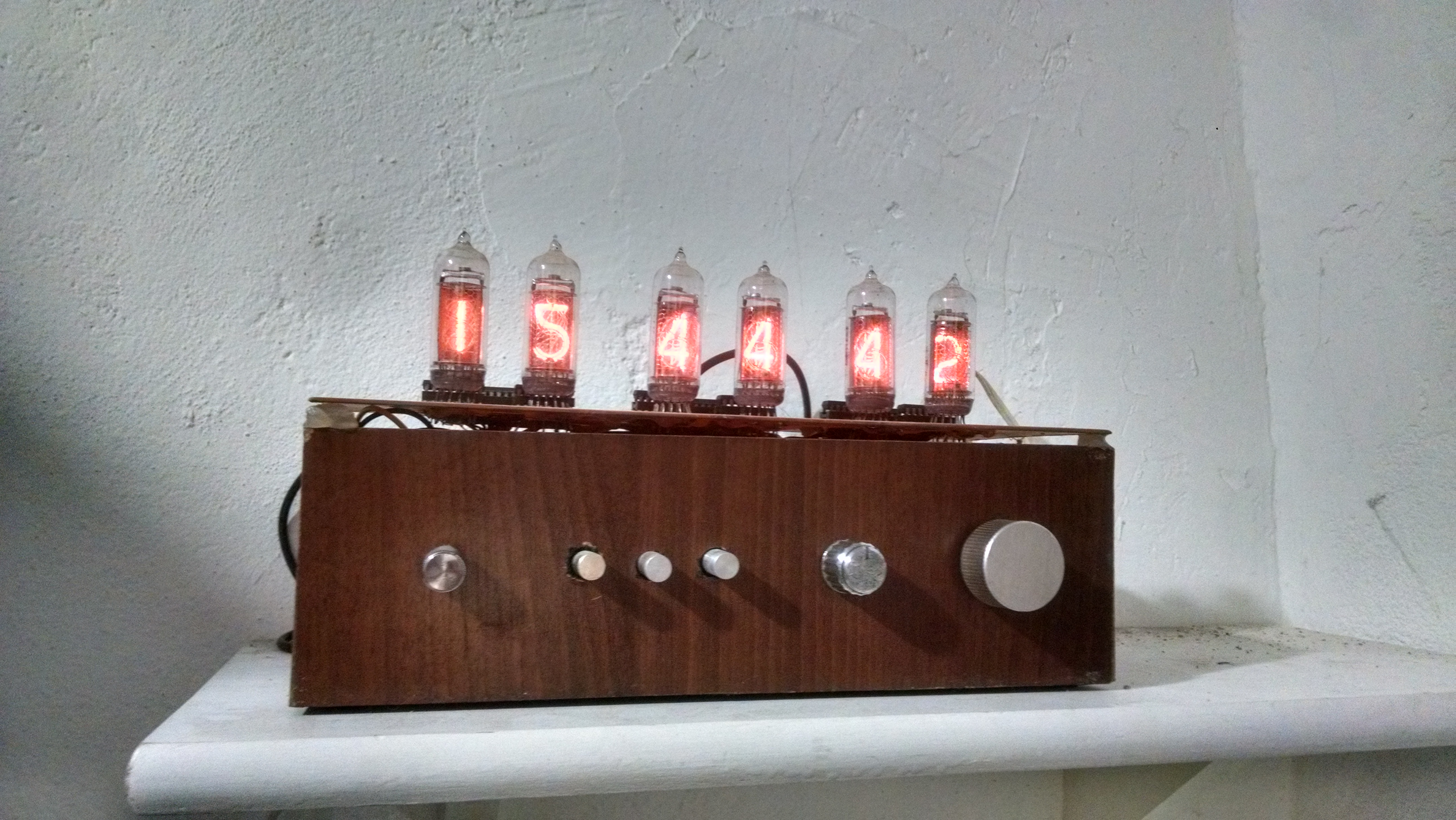
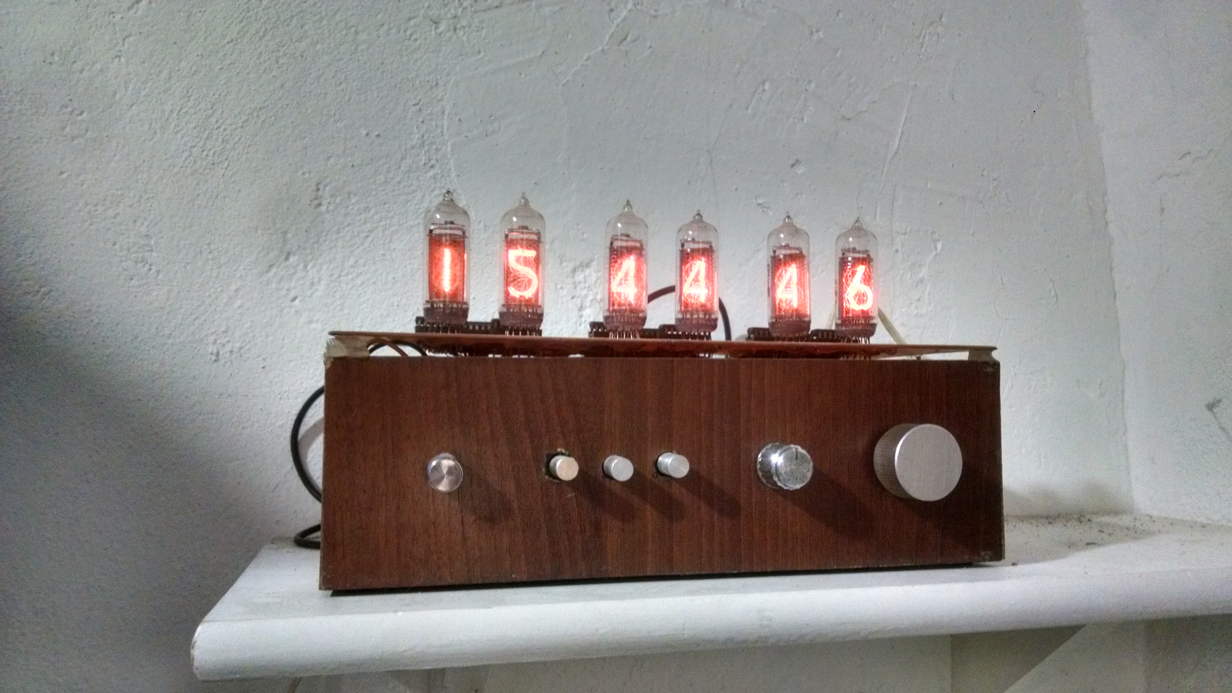
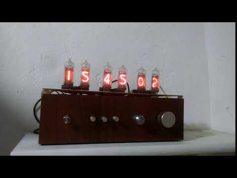
and a video:
| Qty | Value | Footprint | References |
|---|---|---|---|
| 9 | TEST | connect:GS2 | TP1, TP2, TP3, TP4, TP5, TP6, TP7, TP8, TP9 |
| 8 | 100n | smd_capacitors:c_0805 | C1, C2, C4, C5, C11, C12, C13, C14 |
| 8 | 33k | pretty-libs:R0805_smd-mod | R19, R20, R21, R22, R23, R24, R25, R28 |
| 8 | MPSA92 | discret:TO92-CBE | Q1, Q2, Q3, Q4, Q5, Q6, Q7, Q8 |
| 4 | 22k | pretty-libs:R0805_smd-mod | R9, R10, R11, R13 |
| 4 | 330 | pretty-libs:R3-mod | R2, R4, R6, R8 |
| 4 | 330k | pretty-libs:R3-mod | R1, R3, R5, R7 |
| 4 | IN14 | pretty-libs:IN-14-mod | TBE1, TBE2, TBE3, TBE4 |
| 4 | P*** | connect:1pin | 1PIN, 1PIN, 1PIN, 1PIN |
| 3 | 1N5819 | discret:D3 | D1, D2, D3 |
| 3 | SW_PUSH | switch:TL1105L-4,3 | SW1, SW2, SW3 |
| 2 | 220u | capacitors:CP_8x13mm | C3, C7 |
| 2 | BC857 | smd_transistors:sot23 | Q9, Q12 |
| 2 | C | smd_capacitors:c_0805 | C10, C15 |
| 2 | HV5812 | pretty-libs:SO28W-mod | U1, U2 |
| 2 | R | pretty-libs:R3-mod | R26, R27 |
| 1 | 0.22u | ref-packages:C102-054X133 | C8 |
| 1 | 12k | pretty-libs:R3-mod | R17 |
| 1 | 1n | smd_capacitors:c_0805 | C9 |
| 1 | 1u | capacitors:CP_5x6mm | C6 |
| 1 | 2 | pretty-libs:R3-mod | R14 |
| 1 | 220k | pretty-libs:R3-mod | R18 |
| 1 | 220uH | inductors:INDUCTOR_V | L1 |
| 1 | 47k | pretty-libs:R0805_smd-mod | R15 |
| 1 | 560k | pretty-libs:R0805_smd-mod | R12 |
| 1 | 5V1 | discret:D3 | D6 |
| 1 | 75V | discret:D3 | D5 |
| 1 | 820k | pretty-libs:R3-mod | R16 |
| 1 | BARREL_JACK | connect:BARREL_JACK | CON1 |
| 1 | BC847 | smd_transistors:sot23 | Q10 |
| 1 | CONN_5 | pin_array:PIN_ARRAY_5x1 | P1 |
| 1 | DS32kHz | pretty-libs:SO16W-mod | U4 |
| 1 | EGP20D | discret:D3 | D4 |
| 1 | IRF740 | pretty-libs:TO220GDS_VERT | Q13 |
| 1 | IRLML6402 | libcms:SOT23GDS | Q11 |
| 1 | IRS44273 | libcms:SOT23-5 | U6 |
| 1 | LM7805 | powerint:TO-220 | U3 |
| 1 | LOGO | logos:Panda_Logo_7x5mm | Logo_ref |
| 1 | PIC18F1320 | pretty-libs:SO18L-mod | U5 |
| 1 | SWITCH_INV | pretty-libs:CL-SA-12C4-02 | SW0 |
It measures 143.5 × 64.8 mm and has 2 copper layers, 1.6 mm thick.
93 parts, built around the PIC18F1320-E/P, HV5812P-G, DS32KHZS# and LM7805. The full list of its parts is on this page, with links to each part's symbol and footprint where PCBKit's library has them.
From the erickpires/NixieClock repository on GitHub, at the commit this page was made from: the board is kicad_nixie/kicad/Nixie_proj.kicad_pcb. PCBKit opens the board in the browser, with nothing to install.
Its repository publishes it under the MIT licence: you may reuse it on that licence's terms (keep the author's notice, and for a copyleft licence share your changes alike).


dm2lct/tlnixie
PCB files for the Turmlabor nixie clock 2.0

Majklzbastlirny/NixieClock
ESP-IDF firmware for a 6-tube multiplexed ESP32 nixie clock (WiFi/SNTP, Home Assistant, web UI, alarm, temperatures)


MG-5/vfd-clock-hardware
Hardware for controlling six VFD IV-17 tubes as clock (HH:MM:SS)


