

2 layers48.6 × 59.3 mm

 mcskny/wireless-he-macropad
A wireless, 12-key Hall-effect macropad built around a custom PCB, an ESP32-C6 sender, an ESP32-S3 USB receiver, and a native macOS companion app.
Macropad is an open-source printed circuit board by mcskny, from the mcskny/wireless-he-macropad repository on GitHub, published under the GPL-3.0 licence. It is a 4-layer board of 65 × 100 mm with 165 parts on 126 nets, routed with 321 tracks and 94 vias.
It is built around the SN74AHCT1G125DCKR(LX), TCS40DLR,LF and MCP3202-CI/P, with the SN74HC165PWRG3, AP2112K-3.3 and CD74HC4067SM96 among its other parts. Its parts include 42 capacitors, 40 resistors, 35 ICs, 11 diodes and 3 transistors. It belongs with the keyboards and input boards and the ESP32 and RISC-V boards of this library.


Separate transport profiles (experimental): C6 0.1.6 and Studio 0.1.4 keep BLE and ESP-NOW layer settings separately, copying prior shared settings on first migration. Separate key assignments across mode switches were verified on the current hardware. Hall calibration remains shared.
6 November 2026: Studio supports configuring C6 lighting, selecting layers and writing supported per-layer HID assignments over encrypted BLE. Hardware checks confirmed lighting changes on two layers and an H assignment that survived a C6 restart. Three paired-slot names are locally editable aliases, not automatically retrieved host names. BLE sensor telemetry and automatic synchronization between C6 and S3 are not implemented; a solid lighting color also persisted across a restart with Studio closed. Other hosts need further testing.
A wireless, 12-key Hall-effect macropad built around a custom PCB, an ESP32-C6 sender, an ESP32-S3 USB receiver, and a native macOS companion app.
The project explores analog key travel, configurable actuation, per-layer actions, responsive lighting, and power-conscious wireless operation. It is an active hardware and firmware prototype, not a finished commercial product.



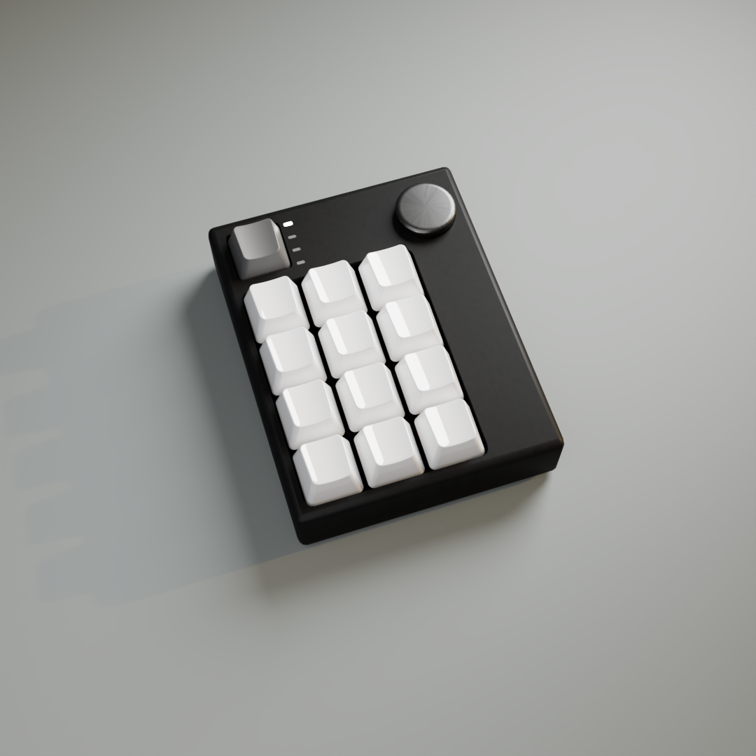 Enclosure and layout | 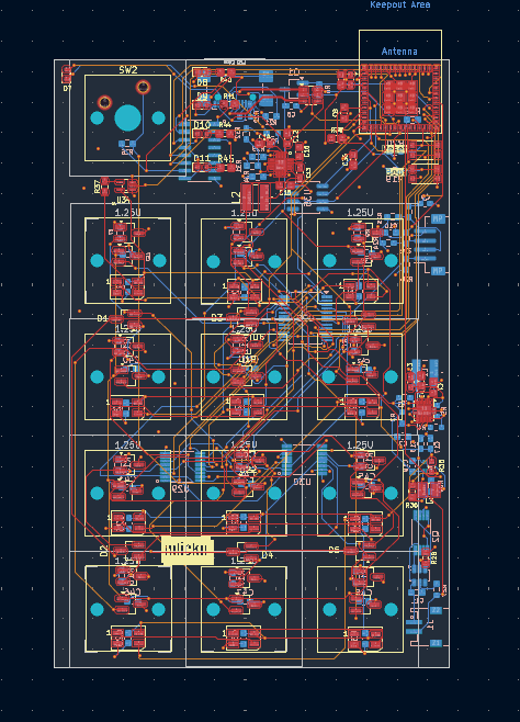 Custom PCB |
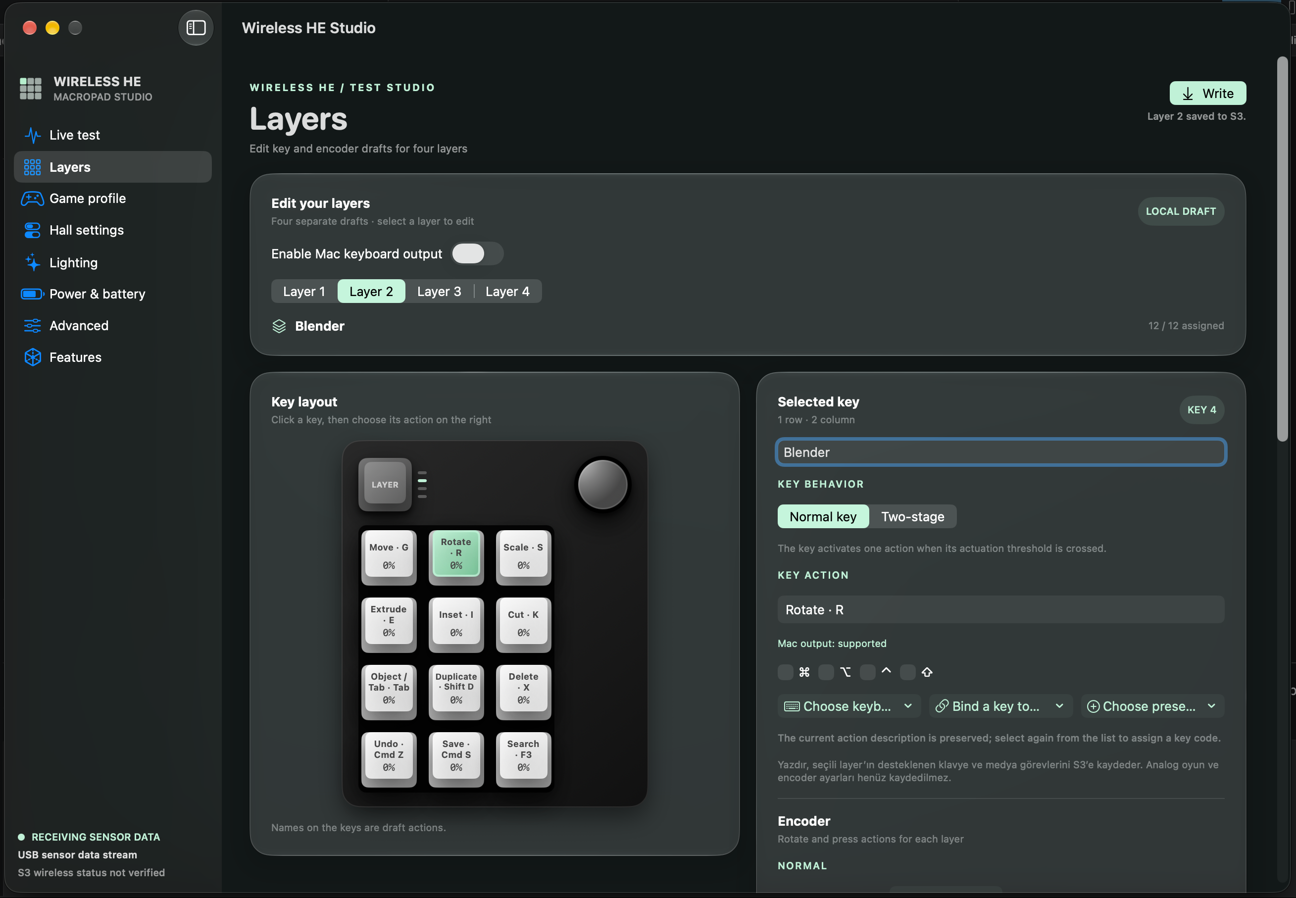 Studio · layers and key assignments | 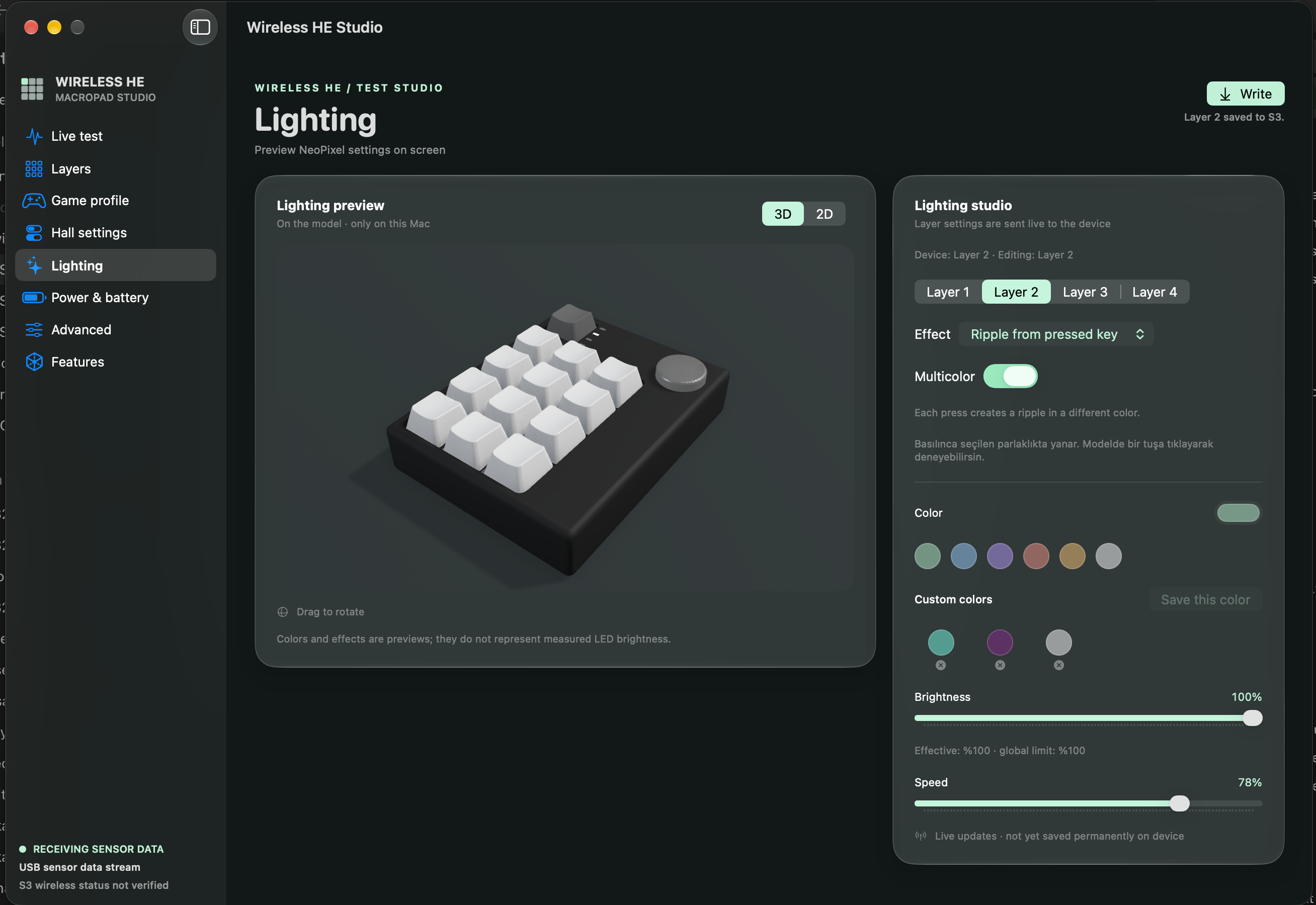 Studio · lighting and 3D preview |
The enclosure and PCB images are renders; Studio screenshots illustrate the interface and may not show its latest revision.
Each key moves a magnet past a Hall sensor. The sensor's analog output is sampled and converted into a calibrated position, allowing the prototype to react to key travel rather than just an on/off switch.
12 × DRV5055 sensors → CD74HC4067 multiplexer → MCP3202 ADC
                                                    │
                                           ESP32-C6 macropad
                                                    │ ESP-NOW
                                                    ▼
Mac / computer ← USB HID + serial telemetry ← ESP32-S3 dongle
        │                                           ▲
        └──── Studio configuration and live lighting ┘
The repository contains both the current C6/S3 test bridge and separate, evolving product-firmware projects. They are not interchangeable builds and do not necessarily use the same pin assignments.
The following describes the test setup and the specific behavior observed, as of 5 November 2026. A successful test of one action does not mean every combination has been validated.
| Area | Observed on the prototype | Still to do |
|---|---|---|
| Sensing | All 12 channels appeared in Studio; individual calibration, channel mapping, and live key movement were checked. | Long-run stability, cross-channel effects, physical travel measurement, and full calibration validation. |
| Wireless link | C6 → S3 → Mac telemetry works; Studio displays scan, submission, reception, and sequence-gap counters. | Reduce active-mode gaps, measure latency and range, and add authenticated pairing/encryption. |
| Direct BLE | C6 paired with a Mac and typed using a saved profile; Layer + KEY 0 switched transport and the transition effects were checked. | Validate persisted bonding across reboot and transport changes, BLE disconnect release, other hosts, latency, and power. |
| USB keyboard | Layer-specific keyboard actions and volume-down HID were tested on a Mac. A saved layer survived an S3 reconnect; output also worked with Studio closed. | More host/shortcut tests, disconnect recovery, and NKRO. The current keyboard report is 6KRO. |
| Hall behaviors | Rapid Trigger retriggering was tested with a partially released key. SOCD's last-pressed priority and return to the held key were also tested. | Wider sensitivity, multi-key, and long-duration hardware tests; two-stage behavior needs a physical test. |
| Lighting | All 12 LEDs lit. Live layer/effect synchronization, rainbow or snake color behavior, and virtual-key ripple triggering were checked. Sweep turn-off and ripple stopping were also checked physically. | Validate the complete effect set and persistence; lighting configuration is currently sent live rather than stored permanently on the device. |
| Power policy | Idle sensor scans and software-controlled MOSFET duty cycling were observed; the app displays commanded gate on-time. | Measure rail voltage, startup/settling, backfeed, actual current, and battery life. |
| Mac app | Live sensor values, 2D/3D views, layer controls, local profiles, and the device write path are available. Blender's move, rotate, and scale actions were tested. | Complete and validate all target-app actions, accessibility, long-term performance, and hardware integration. |
| Mechanical | A 3D model, PCB design, and enclosure renders exist. | Manufacture and validate the plate, case fit, and final assembly. |
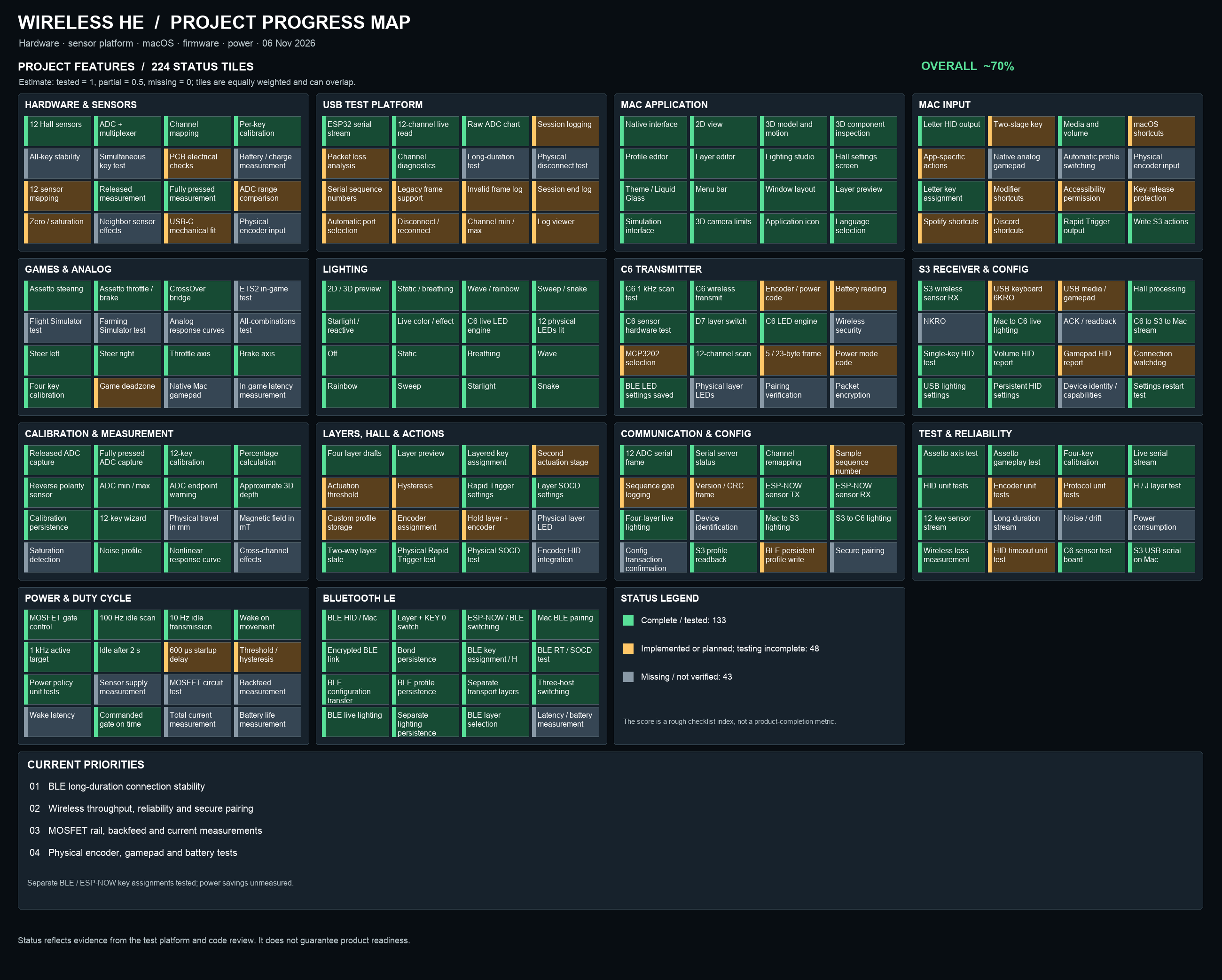
The percentage in the graphic is a manually reviewed, equally weighted checklist estimate. Some items overlap; it is not a measurement of remaining work, reliability, or product readiness. See the compact progress grid for the item index.
Studio is a native SwiftUI / AppKit / SceneKit macOS application. Its current features include:
Studio includes 13 starter profiles covering creative applications and games. The 156 preset entries include direct mappings and suggested shortcuts that may need assignment in the target application; mapping and real application validation are distinct. The UI identifies these assignments. A mapped output does not prove the target application accepts it or that its shortcuts match the user's settings. Encoder actions and native analog gamepad output are not yet implemented end to end.
Studio writes supported actions for the selected layer to the S3. Calibration endpoints and supported Hall settings are included; local profile storage and device storage are distinct. Verify the target layer and assigned shortcuts before writing.
The current test policy scans at 100 Hz while idle, with a 1 kHz active target after detected movement. Idle radio updates are targeted at 10 Hz without Studio or 100 Hz while Studio is connected; active transmission targets 1 kHz. The observed values in Studio are measurements, not guarantees of those targets.
In one active test the C6 reported roughly 983 scans/s and 858 radio submissions/s. These are short observations under specific conditions; submissions, received packets, and end-to-end input latency are different measurements. Sequence gaps can arise in scheduling, radio transmission, buffering, or USB.
With the experimental MOSFET build, the idle test showed approximately 13% commanded gate on-time. Active-mode duty cycling with a 600 µs startup wait reduced a trial to about 620 scans/s, so that experiment was reverted: the current active mode keeps the analog rail commanded on. GPIO timing does not establish the actual rail voltage, energy savings, or battery life. No power-saving multiplier is claimed.
| Component | Role |
|---|---|
| 12 × DRV5055A4 | Analog Hall sensors |
| CD74HC4067 | 16-channel analog multiplexer |
| MCP3202 | 12-bit external ADC |
| XIAO ESP32-C6 | Current wireless sender test board |
| ESP32-S3 | USB receiver and HID test board |
| 12 × SK6812MINI | Addressable key lighting |
| Mechanical switch | Layer button; current test wiring uses D7 to GND |
| Rotary encoder and four indicators | Designed controls; full hardware integration remains in progress |
The test-bridge C6 wiring uses D0–D3 for multiplexer selection, D4 for ADC chip select, D8–D10 for SPI, D6/GPIO16 for LED data, D5/GPIO23 for the optional active-low analog power gate, and D7/GPIO17 for the layer button. Check the bridge documentation, the actual board, and the schematic before connecting or powering anything. These pins are not a promise about the separate product firmware.
| Path | Contents |
|---|---|
Hardware/Kicad/ | PCB and schematic source files |
Firmware/macropad-sender/ | Developing C6 product firmware |
Firmware/dongle-receiver/ | Developing S3 product firmware |
Firmware/shared/ | Shared firmware modules and tests |
examples/c6_s3_sensor_bridge/ | Current C6/S3 wireless prototype and HID bridge |
examples/c6_ble_hid_lab/ | Isolated, buildable BLE HID transport experiment (separate from the integrated C6 build) |
examples/macropad_12_idf/mac_app/ | Wireless HE Studio macOS app |
examples/lighting_espnow_lab/ | Lighting engine and protocol experiments |
examples/crossover_analog/ | Earlier CrossOver analog-controller experiment |
Docs/Proje_Rehberi.md | Detailed Turkish technical guide |
Docs/BLE_Tasarim.md | Direct BLE mode architecture and remaining validation (Turkish) |
output/pdf/Wireless_HE_Proje_Rehberi.pdf | Consolidated project guide (Turkish) |
tools/progress.py | Generates the Turkish project progress map |
The earlier Assetto Corsa steering/throttle/brake experiment used a wired sensor platform and a CrossOver virtual-controller bridge. It does not demonstrate native analog gamepad output from the current S3 dongle.
The prototype firmware has been built with the project's ESP-IDF 6.1 environment. The following examples build only; select the correct board, port, wiring, and configuration before flashing.
# C6 BLE + ESP-NOW test configuration
cd examples/c6_s3_sensor_bridge/c6
idf.py -B build-ble -D SDKCONFIG=sdkconfig.ble build# S3 composite receiver — run from the repository root
cd examples/c6_s3_sensor_bridge/s3_composite
idf.py set-target esp32s3
idf.py buildThe experimental MOSFET build uses a separate power configuration and requires the correct physical switching circuit; see the bridge README before using it. The standard build should not be assumed to have the same gate configuration as the test board.
For the macOS app, see the Studio README. The current local build script targets macOS 26 and expects a configured ESP-IDF Python environment; it is not yet a signed, notarized general distribution.
C6 firmware, S3 firmware, and Studio use separate version numbers and GitHub releases. See release notes, versions, and the developer handoff. Published tags are immutable. Initial releases are pre-releases; the Studio source currently has machine-specific runtime paths, so a portable binary is not claimed.
The project is distributed under the GNU General Public License, version 3 (GPL-3.0-only), unless a file or third-party component specifies different terms. GPLv3 permits commercial use subject to its conditions, including source availability when applicable; no separate commercial permission is required.
Some files carry explicit MIT / MIT-only notices and remain available under those terms (MIT license text). Previously published MIT versions and rights granted under them are unaffected. Third-party components retain their own licenses.
| Qty | Value | Footprint | References |
|---|---|---|---|
| 30 | 0.1u | Capacitor_SMD:C_0603_1608Metric_Pad1.08x0.95mm_HandSolder | C11, C20, C21, C22, C23, C24, C25, C26, C27, C28, C29, C30, C31, C36, C37, C38 +14 |
| 14 | 47K | Resistor_SMD:R_0603_1608Metric_Pad0.98x0.95mm_HandSolder | R7, R8, R9, R10, R11, R12, R13, R14, R15, R16, R17, R18, R25, R26 |
| 12 | 1.25U | afadfsfaf:switchsocket | MX1, MX2, MX3, MX4, MX5, MX6, MX7, MX8, MX9, MX10, MX11, MX12 |
| 12 | DRV5055A4 | Package_TO_SOT_SMD:SOT-23_Handsoldering | U15, U16, U17, U18, U19, U20, U21, U22, U23, U24, U25, U26 |
| 12 | SK6812MINI | LED_SMD:LED_SK6812MINI_PLCC4_3.5x3.5mm_P1.75mm | NEO1, NEO2, NEO3, NEO4, NEO5, NEO6, NEO7, NEO8, NEO9, NEO10, NEO11, NEO12 |
| 12 | TCS40DLR | Package_TO_SOT_SMD:SOT-23_Handsoldering | U2, U3, U4, U5, U6, U7, U8, U9, U10, U11, U12, U13 |
| 11 | 10K | Resistor_SMD:R_0603_1608Metric_Pad0.98x0.95mm_HandSolder | R6, R19, R20, R23, R24, R31, R32, R34, R39, R42, R43 |
| 6 | BAT54A | Package_TO_SOT_SMD:SOT-23_Handsoldering | D1, D2, D3, D4, D5, D6 |
| 5 | LED | LED_SMD:LED_0603_1608Metric | D7, D8, D9, D10, D11 |
| 4 | 270R | Resistor_SMD:R_0603_1608Metric_Pad0.98x0.95mm_HandSolder | R40, R41, R44, R45 |
| 3 | 100K | Resistor_SMD:R_0603_1608Metric_Pad0.98x0.95mm_HandSolder | R30, R36, R38 |
| 2 | 100R | Resistor_SMD:R_0603_1608Metric_Pad0.98x0.95mm_HandSolder | R27, R37 |
| 2 | 10n | Capacitor_SMD:C_0603_1608Metric_Pad1.08x0.95mm_HandSolder | C9, C10 |
| 2 | 10u | Capacitor_SMD:C_0805_2012Metric_Pad1.18x1.45mm_HandSolder | C15, C16 |
| 2 | 2.2u | Capacitor_SMD:C_0603_1608Metric_Pad1.08x0.95mm_HandSolder | C12, C14 |
| 2 | 2.2uF | Capacitor_SMD:C_0603_1608Metric_Pad1.08x0.95mm_HandSolder | C32, C33 |
| 2 | 22u | Capacitor_SMD:C_0603_1608Metric_Pad1.08x0.95mm_HandSolder | C17, C18 |
| 2 | 5,1K | Resistor_SMD:R_0603_1608Metric_Pad0.98x0.95mm_HandSolder | R21, R22 |
| 2 | AO3400A | Package_TO_SOT_SMD:SOT-23 | Q3, Q4 |
| 2 | SN74HC165PWR | SN74HC165PWR:SOP65P640X120-16N | U29, U30 |
| 1 | 1.5K | Resistor_SMD:R_0603_1608Metric_Pad0.98x0.95mm_HandSolder | R33 |
| 1 | 1.5u | 1269AS-H-1R5M_P2:INDC2520X100N | L3 |
| 1 | 10u | Capacitor_SMD:C_0603_1608Metric_Pad1.08x0.95mm_HandSolder | C19 |
| 1 | 18650 Li-ion (3.7V-4.2V) | 648102131822:648102131822 | J1 |
| 1 | 1K | Resistor_SMD:R_0603_1608Metric_Pad0.98x0.95mm_HandSolder | R28 |
| 1 | 2.2u | fssffff:SRN4030HA2R2Y | L2 |
| 1 | 20K | Resistor_SMD:R_0603_1608Metric_Pad0.98x0.95mm_HandSolder | R29 |
| 1 | 47n | Capacitor_SMD:C_0603_1608Metric_Pad1.08x0.95mm_HandSolder | C13 |
| 1 | 750K | Resistor_SMD:R_0603_1608Metric_Pad0.98x0.95mm_HandSolder | R35 |
| 1 | AO3401A | Package_TO_SOT_SMD:SOT-23_Handsoldering | Q1 |
| 1 | AP2112K | AP2112K_3_3TRG1:SOT95P285X140-5N | U36 |
| 1 | BQ25300RTER | ssfsf:QFN50P300X300X80-17N-D | Z1 |
| 1 | Boot_bttn | Button_Switch_SMD:SW_Push_1P1T_NO_CK_KMR2 | SW1 |
| 1 | CD74HC4067SM | Package_SO:SSOP-24_5.3x8.2mm_P0.65mm | U28 |
| 1 | DW01A | Package_TO_SOT_SMD:SOT-23-6 | U32 |
| 1 | ESP32-C6-MINI-1 | RF_Module:ESP32-C6-MINI-1 | U27 |
| 1 | Encoder | Connector_JST:JST_ZH_B4B-ZR-SM4-TF_1x04-1MP_P1.50mm_Vertical | J3 |
| 1 | LOGO | LOGO | |
| 1 | Lay_button | Button_Switch_Keyboard:SW_Cherry_MX_1.00u_PCB | SW2 |
| 1 | MCP3202 | Package_SO:SOIC-8_3.9x4.9mm_P1.27mm | U35 |
| 1 | Reset_bttn | Button_Switch_SMD:SW_Push_1P1T_NO_CK_KMR2 | SW3 |
| 1 | SN74AHCT1G125DCKR | afadfsfaf:DCK5 | U34 |
| 1 | SN74HC595DR | SN74HC595DR:SOIC127P600X175-16N | U14 |
| 1 | TPS61023DRLR | TPS61023DRLR:SOT563-ORI | U33 |
| 1 | USBLC6-2SC6 | Package_TO_SOT_SMD:SOT-23-6 | U31 |
| 1 | USB_C_Receptacle_USB2.0_16P | Connector_USB:USB_C_Receptacle_GCT_USB4110 | J2 |


gasiepgodoy/Open-Source-PLC
Open Source Programmable Logic Controller (Hardware and Software). Based on the Master of Science in Electrical Engineering of João Vitor Rocha Santana

ageppert/Core-64c-Compact-Interactive-Core-Memory-Badge
64 bits of core memory and LEDs to interact with directly using a magnetic wand.

LeoSole423/PCB_SALUS_V3
PCB de control para el robot Ackermann SALUS. Esta revision se inspira en la arquitectura de Hoja-Base, pero usa un ESP32-S3 y se mantiene como un diseno independiente.


ageppert/Core-64-Interactive-Core-Memory-Badge
64 bits of core memory and LEDs to interact with directly using a magnetic wand.

David207025/Venturi
Highly optimized line follower robot controlled by the ESP32-S31-WROOM-3 module
It measures 65 × 100 mm and has 4 copper layers, 1.6 mm thick.
165 parts, built around the SN74AHCT1G125DCKR(LX), TCS40DLR,LF, MCP3202-CI/P and SN74HC165PWRG3. The full list of its parts is on this page, with links to each part's symbol and footprint where PCBKit's library has them.
From the mcskny/wireless-he-macropad repository on GitHub, at the commit this page was made from: the board is Hardware/Kicad/macropad.kicad_pcb and its schematic Hardware/Kicad/macropad.kicad_sch. PCBKit opens the board in the browser, with nothing to install.
Its repository publishes it under the GPL-3.0 licence: you may reuse it on that licence's terms (keep the author's notice, and for a copyleft licence share your changes alike).