2 layers145 × 111.8 mm

 PumaFPV/PMK4
PMK - Full wireless split keyboard
PMK Keyboard is an open-source printed circuit board by PumaFPV, from the PumaFPV/PMK repository on GitHub, published under the MIT licence. It is a 2-layer board of 181.6 × 172.3 mm with 151 parts on 165 nets, routed with 2,416 tracks and 458 vias.
It is built around the ESP32-S2FH4, SN74HC165PWRG3 and MIC5528-3.3YMT-T5, with the SKRPABE010, 2450AT18A100E and USB4510-03-1-A among its other parts. Its parts include 43 diodes, 42 switches, 23 capacitors, 18 resistors and 9 ICs. It belongs with the keyboards and input boards and the ESP32 boards of this library.


PMK - a full wireless HID ecosystem for split keyboards and other fun devices
The goal is to make a suit of wireless devices such as "smart keyboard" (combined mouse and keyboard), gamepad, LEDs, knobs, display, etc
The first step is to make a wireless split keyboard, and then we will see later...
Currently, you can connect up to 8 (software limited) devices per dongle, each of them having up to 8 (software limited) layers. Layers only affect keyboards and LED.
The dongle is "master" ESP32S2/S3, appears as HID (keyboard, mouse and joystick) and as Mass Storage device Class with config files inside. Maybe also store password manager later...
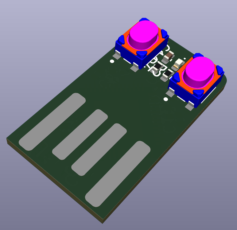
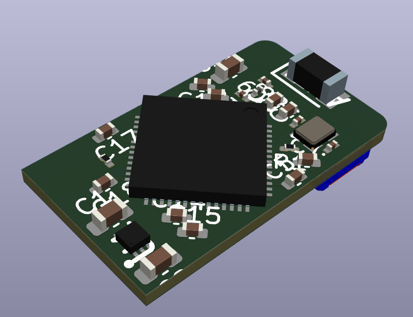
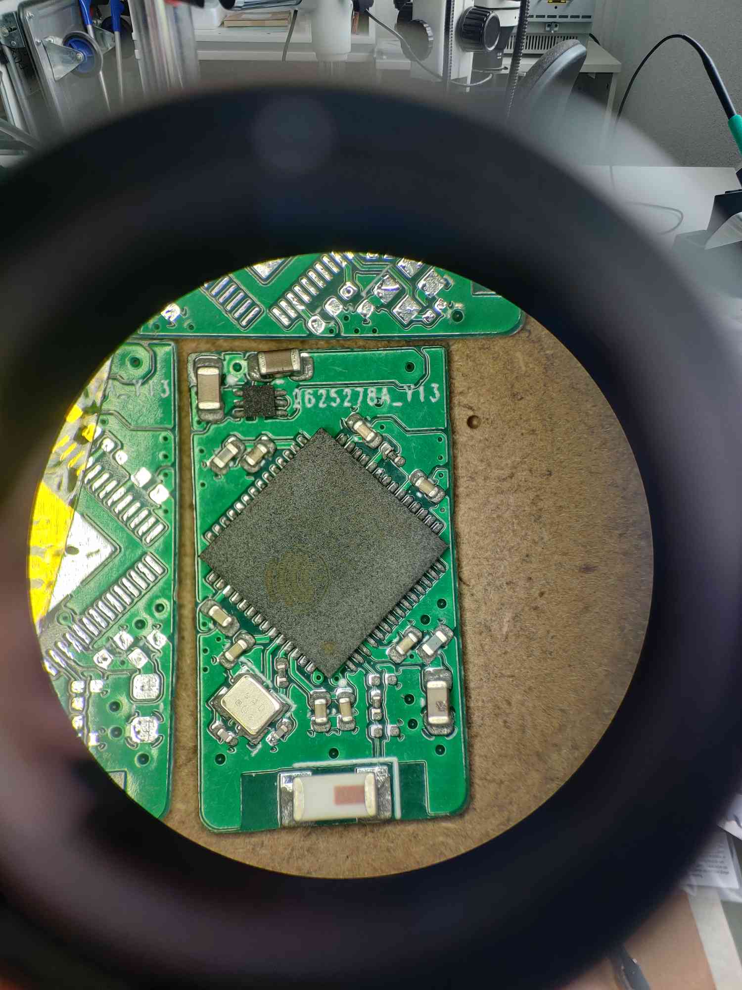
As the dongle is the master of PMK, it hosts the config files for each devices. Here is the expected file organisation:
	|--deviceName1
	|  |- deviceName1.json
	|  |--keyboard
	|  |  |- kb-l1.json
	|  |  |- kb-l2.json
	|  |--led
	|  |  |- led-l1.json
	|  |  |- led-l2.json
	|--deviceName2
	|  |- deviceName2.json
	|  |--keyboard
	|  |  |- kb-l1.json
	|  |  |- kb-l2.json
Exemple file structure can be found here
For more details about devices configurations / capabilities check the Protocol chapter.
Check out the PMK HID keyboard keycodes.md for more information on which code corresponds to which key.
Can run on any espressif chip that can run ESP-NOW. (I will later add support for nRF52 chips for lower power consumption, but it will be incompatible with ESP32 hardware) The plan is to run the simplest firmware on all devices and being able to configure them via their corresponding .json files on the master dongle. Each device should be configurable via UART (set device ID, set dongle MAC address, and read device MAC address). See sample device code for example. (Needs an update)
For example a keyboard would send pressed keys number "0x04, 0xA1", which the dongle then reads in the .json as coordinates for returning desired key "a,b", if special key is pressed (volume up, brighntess control...) then do the appropriate consummer control action. Keys are read with 74HC165 shift registers so theoratically you could have A LOT of keys per keyboard. Current limitation is the max value of keyID which is 255, so there could be a maximum of 255 keys per keyboard (+8 layers...). For more information about the hardawre, check the hardware section. A casing is being designed, it is 3D printable. As foam grid is put inside for better sound (I think it is better?). It support module on the thumb side (Circle trackpad and 3D mouse). Both modules have been tested and work. See Space mouse section for more info.

Mouse can send x,y movement, wheel, pan scrolling and mouse buttons (left, middle, right, forward, backward). Each button is encoded as a bit in the "key" byte of the packet. No configuration needed on the dongle appart from the DPI setting. I plan on retro fitting a wired Logitech G300 with PMK so that it frees up a USB port + becomes wireless. It will be a great first POC. I also have a M330 laying around. It might also end up as a PMK mouse.
Gamepad can send 2 analog joysticks, 2 analog triggers, dpad buttons, and 32 additionnal buttons. No additionnal configuration needed on the dongle. I current upgraded an old thrustmaster sim set (FCS & WCS) from 1992 with PMK. They used to have an ADB port, but now both are fully wireless and appear as one gamepad on the computer. The update is a bit crude as it was first though as a POC for trying out the gamepad feature. But since it works fine, I kept it this way.
(For release 1.2.0) Hopefully processing key press and led function on dongle and send data to device is fast enough, otherwise I will have to run led function on keyboard. (TODO) Buildin keyboard functions: all kb, breath, swipe wave (single color or rainbow), key wave, single key... (TODO / Partially implemented...) Uses the WS2812 kind of LED IC.
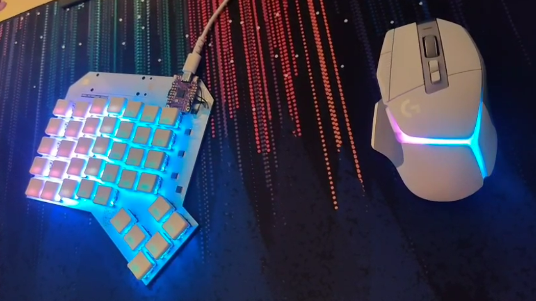
Knobs are in absolute position going from 0 to 255. Could be used for Deej (now only used for deej).
For encoder knobs, this is handled on the device, so it can enumerate as a keyboard pressing one key for clockwise and another for counterclockwise rotation. But it could also be treated as an absolute position depending on the device software.
The software is mostly inspired from Magellan and from reports analysed from a 3DConnexion Space mouse with hid-tool. The current electronics and plastics hardware are from OS3M mouse and it works well. The software still needs some adjustements for calibration. Note: If standard VIK connector is needed, PCB has to be flipped. No special hardware modifications are needed.
This is the packet sent via ESP-NOW. Packet structure is:
| Byte | 1 | 2 | 3-16 |
|---|---|---|---|
| Description | DeviceID | PacketID | Payload |
The goal of this packet strucure is that the dongle knows who is sending data and what kind of data to expect from the payload. The deviceID is mostly used for keyboards and mouse to use the corresponding config files.
the payload's goal is to send data as simple as possible, e.g. keyboard sends key IDs pressed (max 8 at a time) and then the dongle processes the key ID depending on the json configuration
| Packet ID | Packet type | Packet information | Number of bytes | Example packet | Example description |
|---|---|---|---|---|---|
| 0x00 | Telemetry | Send battery voltage, temperature, mac address, errors... | 15 | dID 00 battery temperature address[6] err err err err err | |
| 0x01 | Keyboard | 1 byte = 1 key ID | 8 | dID 01 A2 34 DB 32 21 4F 00 00 | 6 keys are pressed |
| 0x02 | Mouse | move x, move y, wheel, pan, mouse clicks | 7 | dID 02 xx yy ww pp kk | move x relative, move y relative, move w relative, move p relative, kk key press |
| 0x03 | Gamepad | 2 joysticks, 2 analog triggers, 9 directions d pad, 32 buttons | 12 | dID 03 xx yy zz rz rx ry hh bb bb bb bb bb | |
| 0x04 | LED | Choose pre defined function, and R, G and B | 8 | dID 04 func ledNumberStart ledNumberEnd Red Green Blue | |
| 0x05 | Knob / Rotary encoder / potentiometer | each byte is a pot value, max 8 pot per MCU | 10 | dID 05 FF 00 FF 00 FF 00 FF 00 | 4 pots are at max, 4 are at min |
| 0x06 | Actuator | Choose command type (torque, speed, position) | 5 | dID 06 01 | |
| 0x07 | Display | send image to display using wifi for faster refresh rate? or store on local mem | 6 | dID 07 imgNumber x y brightness | Display img number n at coordinates x,y and brightness b. Might change later |
| 0x08 | Serial | send up to 8 bytes of data | 10 | dID 08 aa bb cc dd ee ff gg hh | Sending 8 bytes of data |
| 0x09 | SpaceMouse | send 3 bytes for translation (x, y, z) and 3 bytes for rotation (x, y, z), signed intergers | 6 | dID 7F 00 00 FF 00 00 | Positive translation on x and negative rotation on x |
The dongle supports a few serial commands, they only consist of a string, no CR/LF should be send or the command won't be recongnised. (The received command is hashed into a number then switched cased to the correct function) Here is the list of supported commands:
Before being able to communicate with the dongle, the device has to know the dongle MAC address, and must own a deviceID. You will also need to know the device MAC address to give it to the dongle. Here is the list of supported commands:
Dongle is still HW00 (first rev), it needs 3 small patches to work properly. A HW01 is designed but hasn't been ordered yet. The ESP32S2 has some limitations, so a ESP32S3 dongle is being made too here.
Even a nRF52 dongle might be made... Who knows?
As of today the keyboard is at the HW02 stage, and uses the sofle layout (which I do like). It uses 29 hot swappable Kailh Choc switches + one rotary encoder. The MCU is a PSoM module (homemade SoM) with an ESP32S2 inside. The SoM allows for quick swap of different MCU to try out different feature. Today the ESP32S2 is used for the ease of software developpement. Its power consumption is bad I am aware. But at least software works. Here is the changelog.
| HW rev | change list |
|---|---|
| HW00 | Based on moonlander layout, integrated ESP32, used as a proof of concept, didn't like the layout in the end |
| HW01 | Based on Sofle, PSoM connector (swappable uC for futur proofing), added rotary encoder, way better layout in my opinion. Added side connector option for trackpad or space mouse |
| HW02 | Still soffle, added support for kailh choc V2 (failed), moved the rotary encoder up, added debouncing for rotary encoder, fixed the side module connector, moved test point to accessible location, updated PSoM pinout for better compatibility |
| HW03 (WIP) | Still soffle, fixed the silkscreen, Added slot for dongle, fixed V2 footprint, magnetic pogo module? |
More info on Notion
If you want to make your own keyboard, or visualize current dongle, keyboard or other devices you will need KiCAD 8 and Component_lib which is my own components library. It can be found in its own repo, information on own to install it can be found there.
This whole project is built using PlatformIO on VS Code / VS Codium. (If using VS Codium note that the marketplace for extensions doesn't really work, you will need to download cpp and platformIO .vsix extension files from https://marketplace.visualstudio.com/vscode)
Once this is installed you can clone PMK's repo git clone https://github.com/PumaFPV/PMK
and open whichever code you want to build / modify: PMK/Software/PMK_keyboard with platformIO "Open project".
Once project is opened and loaded (might take a few minutes for the first time) (it needs internet connection to download library and toolchain) you can compile with ctrl + shift + B or ctrl + shift + U to compile and upload, or use the bottom ribbon (make sure to select the correct workspace before compiling and uploading).
| Qty | Value | Footprint | References |
|---|---|---|---|
| 40 | YF923_2020_WS2812_LED | Component_lib:YF923_2020_WS2812_LED_DUALSIDE | D601, D602, D603, D604, D605, D606, D607, D608, D609, D610, D611, D612, D613, D614, D615, D616 +24 |
| 39 | SW_Push | Component_lib:Kailh_socket_PG1350_reversible | SW502, SW503, SW504, SW505, SW506, SW507, SW508, SW509, SW510, SW511, SW512, SW513, SW514, SW515, SW516, SW517 +23 |
| 9 | 100n | Capacitor_SMD:C_0402_1005Metric | C403, C404, C405, C408, C411, C412, C414, C415, C416 |
| 5 | EXB-2HV103JV | Component_lib:EXB2HV_1 | RN501, RN502, RN503, RN504, RN505 |
| 5 | SN74HC165PWR | Component_lib:SOP65P640X120-16N | U501, U502, U503, U504, U505 |
| 4 | 2u2 | Capacitor_SMD:C_0603_1608Metric | C301, C302, C303, C304 |
| 4 | nu | Resistor_SMD:R_0201_0603Metric | R405, R406, R407, R408 |
| 3 | LED | Component_lib:LED_0402_1005Metric_DUALSIDE | D201, D202, D401 |
| 2 | 10k | Resistor_SMD:R_0201_0603Metric | R403, R404 |
| 2 | 15p | Capacitor_SMD:C_0201_0603Metric | C401, C402 |
| 2 | 1k5 | Resistor_SMD:R_0402_1005Metric | R205, R206 |
| 2 | 1u | Capacitor_SMD:C_0402_1005Metric | C410, C413 |
| 2 | 4u7 | Capacitor_SMD:C_0603_1608Metric | C201, C203 |
| 2 | 5.1k | Resistor_SMD:R_0201_0603Metric | R101, R102 |
| 2 | C | Capacitor_SMD:C_0201_0603Metric | C406, C407 |
| 2 | LOGO | Component_lib:puma_logo_14mm | G***, G*** |
| 2 | MIC5528-3.3YMT-T5 | Component_lib:SON40P120X120X60-7N-D | U301, U302 |
| 2 | SKRPABE010 | Component_lib:SKRPABE010 | S401, S402 |
| 1 | 0 | Resistor_SMD:R_0201_0603Metric | R401 |
| 1 | 0 | Resistor_SMD:R_0402_1005Metric | R201 |
| 1 | 0k | Resistor_SMD:R_0201_0603Metric | R301 |
| 1 | 100k | Resistor_SMD:R_0402_1005Metric | R207 |
| 1 | 10u | Capacitor_SMD:C_0603_1608Metric | C409 |
| 1 | 1k1 | Resistor_SMD:R_0402_1005Metric | R204 |
| 1 | 1u | Capacitor_SMD:C_0603_1608Metric | C202 |
| 1 | 2450AT18A100E | Component_lib:ANTC3216X140N | ANT401 |
| 1 | 2k | Resistor_SMD:R_0402_1005Metric | R402 |
| 1 | 36k5 | Resistor_SMD:R_0402_1005Metric | R202 |
| 1 | 590 | Resistor_SMD:R_0402_1005Metric | R203 |
| 1 | BQ24075RGTR | Component_lib:QFN50P300X300X100-17N-D | U201 |
| 1 | Battery_Cell | Component_lib:BatteryHolder_Keystone_1042_1x18650_DUALSIDE | BT101 |
| 1 | Conn_01x03_Socket | Connector_PinHeader_2.54mm:PinHeader_1x03_P2.54mm_Vertical | J402 |
| 1 | Conn_01x08_Female | Connector_PinHeader_1.27mm:PinHeader_1x08_P1.27mm_Vertical | J401 |
| 1 | Crystal_GND24_Small | Component_lib:Crystal_SMD_2016-4Pin_2.0x1.6mm | Y601 |
| 1 | ESP32-S2FH4 | Component_lib:QFN40P700X700X90-57N-D | U401 |
| 1 | L | Inductor_SMD:L_0201_0603Metric | L401 |
| 1 | LOGO | Component_lib:pmk-v1-noFN_180mm | G*** |
| 1 | SW_Push | Component_lib:SKRPABE010 | SW501 |
| 1 | TestPoint | TestPoint:TestPoint_Pad_D1.0mm | TP201 |
| 1 | USB4510-03-1-A | Component_lib:USB4510031A | J101 |


PumaFPV/PSoM
PSoM, either Pico System On Module, or Puma System On Module for those who prefer


gasiepgodoy/Open-Source-PLC
Open Source Programmable Logic Controller (Hardware and Software). Based on the Master of Science in Electrical Engineering of João Vitor Rocha Santana

mcskny/wireless-he-macropad
A wireless, 12-key Hall-effect macropad built around a custom PCB, an ESP32-C6 sender, an ESP32-S3 USB receiver, and a native macOS companion app.

ollieelliot/ESP32-IoT-Board
Challenging myself to make a tiny IoT device. Currently 22.8 mm in diameter, ~45 components, 2.4 Ghz chip antenna, microphone, temperature sensor, ESP32-C3 and LiPo charger circuit.

matveylapin/CopterCat_cm4
Полётный контроллер для стандарта FMU-v6u. Обычно на дронах для программирования устанавливают полётный контроллер, одноплатный компьютер и иногда arduino.


ben5049/Keyboard
Features: - Wireless - 900mAh battery - Bluetooth (nRF52) - ZMK - 4 Port USB hub - BLDC Knob for haptic feedback - Kailh Choc V1 switches
It measures 181.6 × 172.3 mm and has 2 copper layers, 1.6 mm thick.
151 parts, built around the ESP32-S2FH4, SN74HC165PWRG3, MIC5528-3.3YMT-T5 and SKRPABE010. The full list of its parts is on this page, with links to each part's symbol and footprint where PCBKit's library has them.
From the PumaFPV/PMK repository on GitHub, at the commit this page was made from: the board is Hardware/PMK_Keyboard/PMK_Keyboard_HW00/PMK_Keyboard.kicad_pcb and its schematic Hardware/PMK_Dongle/PMK_Dongle_C_nRF_HW00/PMK_Dongle_C_nRF_HW00.kicad_sch. PCBKit opens the board in the browser, with nothing to install.
Its repository publishes it under the MIT licence: you may reuse it on that licence's terms (keep the author's notice, and for a copyleft licence share your changes alike).