4 layers65 × 100 mm
Macropad
mcskny/wireless-he-macropad
A wireless, 12-key Hall-effect macropad built around a custom PCB, an ESP32-C6 sender, an ESP32-S3 USB receiver, and a native macOS companion app.
165 partsGPL-3.0

 Victor-Field/Andotrope2
DIY open source andotrope
Abdotrope is an open-source printed circuit board by Victor-Field, from the Victor-Field/Andotrope repository on GitHub. It is a 2-layer board of 48.6 × 59.3 mm with 31 parts on 32 nets, routed with 413 tracks and 45 vias.
It is built around the TCS40DLR,LF, MCP73831T-2ACI/OT-HXY and MIC5504-3.3YM5-TR, with the RP2040-ZERO among its other parts. Its parts include 12 resistors, 7 capacitors, 4 ICs, 2 connectors and 1 diode. It belongs with the RP2040 boards of this library.


Open Source andotrope I made, for anyone that wants to build their own andotrope. Credit to the idea of an andotrope goes to Mike Ando https://www.riumplus.com/gehns-holographic-imager-andotrope/ I came up with the method of creating the see through effect.
This is just a prototype and certain things don't work properly yet, please read the issues.
We use a rp2040 zero as the main microcontroller.
Here's a link to the specific screens i bought: https://nl.aliexpress.com/item/1005004662221931.html?spm=a2g0o.order_list.order_list_main.45.342279d2Cq6V3n&gatewayAdapt=glo2nld
Here's a link for the specific motor I bought: https://nl.aliexpress.com/item/4001118243931.html?spm=a2g0o.order_list.order_list_main.50.342279d2Cq6V3n&gatewayAdapt=glo2nld
Here's a link for the specific magnets I bought: https://www.digikey.be/nl/products/detail/radial-magnets-inc/8996/5126078
Here's a link for the specific power connector I bought for the motor: https://www.digikey.be/nl/products/detail/tensility-international-corp/54-00287/16649080
The powerbrick isn't for sale anymore so you'll have to buy your own 6V barrel connector powerbrick.
Here's the link for the polarised film I used: https://nl.aliexpress.com/item/1005006054349865.html?spm=a2g0o.order_list.order_list_main.5.342279d2Cq6V3n&gatewayAdapt=glo2nld
Unfortunately the screens themselves are polarised at a 45° angle so you'll have to add another polarisation filter on top if it polarising it horizontally or vertically so the wrap around filter doesn't block the light coming from the filter at the opposite side of the screen holder but only blocks light from the screen itself.
here's the heat inserts I used: https://nl.aliexpress.com/item/1005003582355741.html?spm=a2g0o.order_list.order_list_main.23.342279d2Cq6V3n&gatewayAdapt=glo2nld
Here's the screws I used for the heat inserts: https://nl.aliexpress.com/item/1005005070119421.html?spm=a2g0o.order_list.order_list_main.11.342279d2Cq6V3n&gatewayAdapt=glo2nld
I sourced the powerswitch from old christmas lights and soldered it in between the batteries power line.
The rest of the components you should be able to source from the bill of materials of the scematic.
Here's some more important tips:
Do not solder the mosfet to the bord but rather bridge the source and drain. I myself glued the screens to the screen holder using double sided tape. The polarised film has a protective film on both sides that needs to be removed, be carefull because one side of the film is very sticky and should be oriented inwards. This sticky side does help with sticking it to the screens but not to the outside of the screen holder. I used zip ties for that.
| Qty | Value | Footprint | References |
|---|---|---|---|
| 6 | 10k | Resistor_SMD:R_0402_1005Metric_Pad0.72x0.64mm_HandSolder | R3, R8, R10, R11, R12, R13 |
| 2 | 0.47 µF | Capacitor_SMD:C_0402_1005Metric_Pad0.74x0.62mm_HandSolder | C3, C4 |
| 2 | 1 μF | Capacitor_SMD:C_0402_1005Metric_Pad0.74x0.62mm_HandSolder | C1, C2 |
| 2 | 10 | Resistor_SMD:R_0402_1005Metric_Pad0.72x0.64mm_HandSolder | R1, R2 |
| 2 | 4,7 μF | Capacitor_SMD:C_0603_1608Metric_Pad1.08x0.95mm_HandSolder | C5, C6 |
| 2 | 4,7k | Resistor_SMD:R_0402_1005Metric_Pad0.72x0.64mm_HandSolder | R4, R5 |
| 2 | 5051101892 | ffc molex:CON_5051101892_MOL | scherm1connector1, scherm2connector1 |
| 2 | TCS40DLR | hall sensor:SOT-23F_TOS | U2, U3 |
| 1 | 100 | Resistor_SMD:R_0402_1005Metric_Pad0.72x0.64mm_HandSolder | R6 |
| 1 | 100nF | Capacitor_SMD:C_0402_1005Metric_Pad0.74x0.62mm_HandSolder | C7 |
| 1 | 2.8k | Resistor_SMD:R_0402_1005Metric_Pad0.72x0.64mm_HandSolder | R7 |
| 1 | LED | LED_SMD:LED_0603_1608Metric_Pad1.05x0.95mm_HandSolder | D1 |
| 1 | LOGO | andotrope:teeth | G*** |
| 1 | MCP73831T-2ACI/OT | battery manager:SOT-23-5_MC_MCH | U4 |
| 1 | MEM2067-02-180-00-A_REVB | micro sd card reader:GCT_MEM2067-02-180-00-A_REVB | J3 |
| 1 | MIC5504-3.3YM5-TR | battery manager:SOT-23-5_MC_MCH | U1 |
| 1 | PMOS (SSM3J372R) | mosfet:SOT-23F_TOS | Q1 |
| 1 | RP2040-Zero | RP2040-Zero-Kicad-main:RP2040-Zero | RZ1 |
| 1 | S2B-PH-K-SLFSN | battery connector:CONN_S2B-PH-K-S_JST | J1 |
mcskny/wireless-he-macropad
A wireless, 12-key Hall-effect macropad built around a custom PCB, an ESP32-C6 sender, an ESP32-S3 USB receiver, and a native macOS companion app.

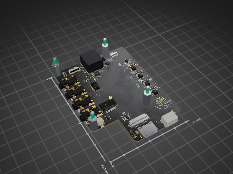
loopj/short-stack
World's Smallest Nintendo Wii, using a trimmed motherboard and custom stacked PCBs

MicroCoreLabs/Projects
Ted Fried's MicroCore Labs Projects - FPGA CPU cores and emulators for the 8088, 8086, 8051, 6502, 68000, Z80, Risc-V, and also Typewriter and EPROM Emulator projects.

tinyfpga/TinyFPGA-B-Series
Open source design files for the TinyFPGA B-Series boards.


alvarop/swd2usbc
Have you ever wanted to debug your device over USB-C? Sometimes there's not enough room for a JTAG/SWD connector, or even Tag-Connect pads!
It measures 48.6 × 59.3 mm and has 2 copper layers, 1.6 mm thick.
31 parts, built around the TCS40DLR,LF, MCP73831T-2ACI/OT-HXY, MIC5504-3.3YM5-TR and RP2040-ZERO. The full list of its parts is on this page, with links to each part's symbol and footprint where PCBKit's library has them.
From the Victor-Field/Andotrope repository on GitHub, at the commit this page was made from: the board is Kicad schematics/abdotrope.kicad_pcb and its schematic Kicad schematics/abdotrope.kicad_sch. PCBKit opens the board in the browser, with nothing to install.
Its repository states no licence, so its author keeps all rights: ask Victor-Field before reusing the design.