2 layers100 × 62.1 mm
 MattisLind/teleprinterHat6
A RaspberryPi HAT that interfaces a old school teleprinter
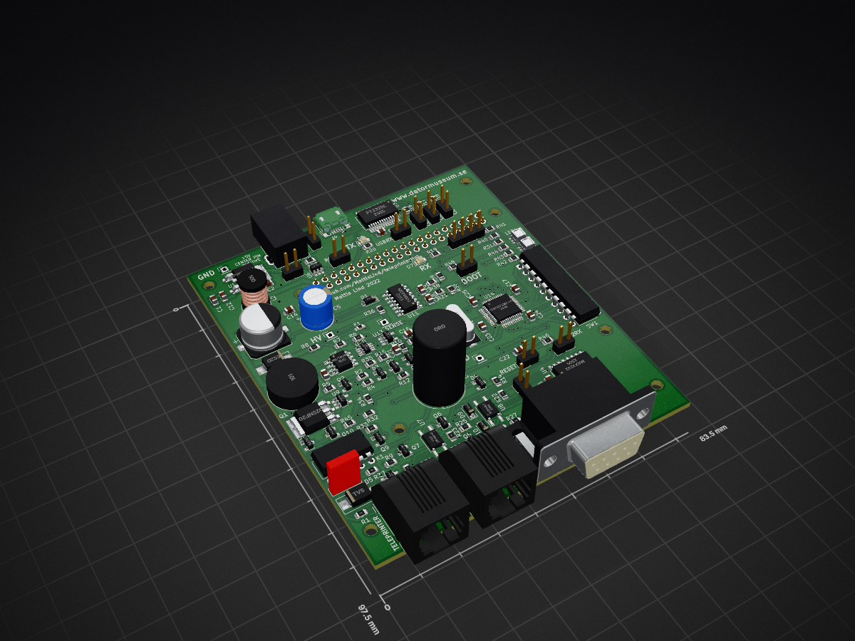
TeleprinterHat is an open-source printed circuit board by MattisLind, from the MattisLind/teleprinterHat repository on GitHub. It is a 2-layer board of 83.5 × 97.5 mm with 145 parts on 169 nets, routed with 1,393 tracks and 166 vias.
It is built around the MAX3232ID, FT232RL and MC34063, with the MCP6004-E/P, 74LVC1G04Z and SFH690BT among its other parts. Its parts include 48 resistors, 25 capacitors, 13 ICs, 12 diodes and 11 connectors. It belongs with the STM32 boards of this library.


A RaspberryPi HAT that interfaces a old school teleprinter


Some time ago I started planning to get an old Lorenz Lo15 teleprinter working. Then arose the question about how to interface those old machines to the real world. While investigating this I gained quite some knowledge of teleprinter interfacing and Telex networks. For example the normal line voltage of a US teleprinter line is 120VDC and the current is 60 mA.
Preferbly the interfacing should be as simple and small as possible. Using some big expensive 50 Hz 120 VAC transformer, rectifier and 2kOhm 6W resistor was not on the table.
Preferbly the circuit should be able to run off a standard USB charger. I.e. 5V 500mA. Experimenting a bit with a stepup circuit gave that is perfectly possibly to step up 5V to 120V. SO one could ask how could a 5V 500 mA supply be able to supply the power for a 120V 60mA load. Of course it cannot, but the problem lies in the fact tat most of the power is absorbed in the current limiting 2kOhm resistor of the old school circuit. The actual teleprinter has an internal resistance of approximately 100 Ohm. So why 120V? The reason for 120V is to achieve a fast pull of the magnet inside the teleprinter. After the initial pull the steady state voltage drop is between 5 to 10 V at 60mA.
When I started to work with this project I also made an announcment in the i-Telex forum and got a reply from Jochen that had done something similar and the same point in time. What a coincidence! piTelex project
Jochen have compiled a lot of interesting and useful information there but the project is based on a Raspberry Pi and cannt be used stand alone. One of my requirements are that it should be able to run completely stand alone. I don't want the bloat of a Linux kernel just to push a few bytes back and forth!
So I put together a list of requirments
The first thing to verify is that the idea of the step up converter was ok. I did a small circuit board to check the circuit and during this I found that the parameters of the coil si very importantant. It has to have a high enough Isat. Then the choice of MOSFET is important. The MOSFET has to full turn on at only 5V gate voltage which is what is available in this circuit. Thus Vgs(ON) is of high interest. Then to deliver as much of the 5V into the coil means that as little loss of energy in the MOSFET is important. The rDS(ON) is the parameter to look for.

It turned out that this circuit worked well and could easily deliver 120VDC.
The main idea with this circuit is to generate the required 60mA with as litle loss as possible. By measuring the current in the loop using a small resistance and then hysteresis regulate the current using a PNP transistor as switch. The current is feed through a small inductor which will not saturate.
As the switch transistor is swithced on the current in the inductor will increase with time. When it reach the upper hysteresis limit the transistor will switch off. The current in the inductance will continue to flow through the diode and the resistor. As the current reaches the lower limit the transistor will switch on again.
The receiver magnet inductance will only come into play when going from sending a space bit to a mark bit. Then the large total inductance will keep the regulator switched on for several milliseconds depending on the inductance in the magenet. As soon as the line current level is reached the magnetcoil is fully saturated and will act as a pure resistance. The implementation is based on a op-amp for measuring the differential volatage of the current measuring resistor. Then a fast comparator with a 5% hysterisis band generates a square wave from the incoming sawtooth signal. This squarewave then drives the switch transistors.
The transistor switch is composed of a PNP transistor as the main switch transistor and a NPN level cvonversion transistor driving the PNP transistor through a resistance.
The reference voltage to the hysteresis comparator is supplied from a PWM signal output of the mikroprocessor. Thereby making it possible to control the current level through software. The PWM signal is low pass filtered in a simple RC network and then buffered through a buffering op-amp.
I did a quick mockup with components at hand but it turned out that the comparator needed to be pretty fast and the transistor switch as well. It simply didn't work very well. I decided to try to do simulations in LTspice before doing further breadboarding.
Searches on internet gave a decent circuit for a P-MOS FET based switch. Simulations in LTspice gave proper values for resistors and capacitors and it was time to make a peroper board.

Schematic.

The design also included an PNP and NPN transistor to handle keying of the sening signal.
A simple NPN transistor is used to key the current in the loop ON/OFF. This has to be done without any free-wheeling diode since otherwise the release of the magnet when swithcing of the current will be very much delayed and might not even happen at all.
Initial tests showed good performance. It could regulate the desired current at varying line voltages without any problem.

This picture show the voltage over the measurement resistor. The scale is 100mV per division and the resistor is 51 ohm so the interval it is regulating over is +/- 2mA as designed.
Running the circuit with the actual Lorenz Lo15 teleprinter also yielded good results.

Keying the signal, 90V line voltage, 40 mA line current. The large spikes are created by the selector magnet as the switch cuts off. Had initial problems that the choosen PNP transistor was unable to cope with these. Intalled a 300 V PNP transistor and a MOV to handle the spikes. Worked well. But I am considering using a TVS instead.

This picture shows when regulating the 40mA output to the selector magnet when the line is in marking state.
I already did a prototype of the step-up converter. But the MOSFET used was quite big and overdimensioned. I also wanted to use a proper gate driver as well as off load the micro controller doing the chore of keeping the PWM rate continuosly measuring the output voltage. A separate, very small, switch control IC, cheap as well, was a better choice. So I designed another prototype board to test out these concept as well as testing the current loop circuit.

| Qty | Value | Footprint | References |
|---|---|---|---|
| 11 | 100n | Capacitor_SMD:C_0805_2012Metric | C1, C6, C7, C8, C9, C13, C15, C17, C23, C24, C25 |
| 8 | 1k | Resistor_SMD:R_0805_2012Metric | R2, R4, R14, R21, R22, R27, R38, R45 |
| 8 | 470 | Resistor_SMD:R_0805_2012Metric | R19, R20, R31, R40, R41, R42, R43, R44 |
| 8 | MountingHole | MountingHole:MountingHole_2.7mm_M2.5 | H1, H2, H3, H4, H5, H6, H7, H8 |
| 7 | 4.7k | Resistor_SMD:R_0805_2012Metric | R3, R10, R16, R17, R18, R25, R29 |
| 4 | Conn_01x01_Male | Connector_PinHeader_2.54mm:PinHeader_1x01_P2.54mm_Vertical | J8, J9, J10, J11 |
| 3 | 1.8k | Resistor_SMD:R_0805_2012Metric | R12, R13, R37 |
| 3 | 10k | Resistor_SMD:R_0805_2012Metric | R26, R46, R48 |
| 3 | 120k | Resistor_SMD:R_0805_2012Metric | R5, R6, R8 |
| 3 | 1n | Capacitor_SMD:C_0805_2012Metric | C14, C16, C21 |
| 3 | 30k | Resistor_SMD:R_0805_2012Metric | R15, R30, R39 |
| 3 | 4.7u | Capacitor_SMD:C_0805_2012Metric | C2, C18, C19 |
| 3 | BAS21 | Package_TO_SOT_SMD:SOT-23 | D3, D4, D12 |
| 3 | FMMT625 | Package_TO_SOT_SMD:SOT-23 | Q3, Q4, Q10 |
| 2 | 10 | Resistor_SMD:R_0805_2012Metric | R7, R11 |
| 2 | 18p | Capacitor_SMD:C_0805_2012Metric | C10, C11 |
| 2 | 74LVC1G04 | Package_TO_SOT_SMD:SOT-23-5_HandSoldering | U2, U13 |
| 2 | CL | Connector_PinHeader_2.54mm:PinHeader_1x02_P2.54mm_Vertical | JP13, JP17 |
| 2 | D_Small | Diode_SMD:D_SOD-123 | D9, D10 |
| 2 | LED_RGB | LED_SMD:LED_Avago_PLCC6_3x2.8mm | LED1, LED2 |
| 2 | MMBT5551L | Package_TO_SOT_SMD:SOT-23 | Q5, Q6 |
| 2 | RJ12 | Connector_RJ:RJ12_Amphenol_54601 | J1, J2 |
| 2 | SFH690BT | Package_SO:SO-4_4.4x3.6mm_P2.54mm | U7, U8 |
| 1 | 1.2k | Resistor_SMD:R_0805_2012Metric | R35 |
| 1 | 1.8 nF | Capacitor_SMD:C_0805_2012Metric | C3 |
| 1 | 1000u | Capacitor_SMD:CP_Elec_10x7.7 | C4 |
| 1 | 100m | Fuse:Fuse_0603_1608Metric_Pad1.05x0.95mm_HandSolder | F1 |
| 1 | 100u | General:Wurth TIF Radial 1018 | L1 |
| 1 | 10u | Capacitor_SMD:C_0805_2012Metric | C12 |
| 1 | 10u | Capacitor_THT:CP_Radial_D8.0mm_P3.50mm | C5 |
| 1 | 10uH | Inductor_THT:L_Radial_D7.0mm_P3.00mm | L2 |
| 1 | 150 | Resistor_SMD:R_0805_2012Metric | R23 |
| 1 | 1M | Resistor_SMD:R_0805_2012Metric | R47 |
| 1 | 1n | Capacitor_THT:C_Rect_L7.0mm_W2.0mm_P5.00mm | C20 |
| 1 | 1u | Capacitor_SMD:C_0805_2012Metric | C22 |
| 1 | 2.4k | Resistor_SMD:R_0805_2012Metric | R36 |
| 1 | 24LC32AT-IOT | Package_TO_SOT_SMD:SOT-23-5_HandSoldering | U6 |
| 1 | 3.3V | Diode_SMD:D_SOD-123 | D1 |
| 1 | 3.3k | Resistor_SMD:R_0805_2012Metric | R33 |
| 1 | 33 | Resistor_SMD:R_0805_2012Metric | R28 |
| 1 | 330 | Resistor_SMD:R_0805_2012Metric | R1 |
| 1 | 33k | Resistor_SMD:R_0805_2012Metric | R32 |
| 1 | 33m | Inductor_THT:L_Radial_D12.0mm_P6.00mm_MuRATA_1900R | L4 |
| 1 | 3k | Resistor_SMD:R_0805_2012Metric | R9 |
| 1 | 51 | Resistor_SMD:R_0805_2012Metric | R34 |
| 1 | 680 | Resistor_SMD:R_0805_2012Metric | R24 |
| 1 | 8MHz | Crystal:Crystal_SMD_HC49-SD | Y1 |
| 1 | BOOT | Connector_PinHeader_2.54mm:PinHeader_1x02_P2.54mm_Vertical | JP19 |
| 1 | CONF0 | Connector_PinHeader_2.54mm:PinHeader_1x02_P2.54mm_Vertical | JP4 |
| 1 | CONF1 | Connector_PinHeader_2.54mm:PinHeader_1x02_P2.54mm_Vertical | JP5 |
| 1 | CONF2 | Connector_PinHeader_2.54mm:PinHeader_1x02_P2.54mm_Vertical | JP6 |
| 1 | DC_JACK | Connector_BarrelJack:BarrelJack_Wuerth_6941xx301002 | J3 |
| 1 | EA2-5NU | Package_DIP:DIP-10_W7.62mm | K1 |
| 1 | ES2D | Diode_SMD:D_SMB_Handsoldering | D2 |
| 1 | FMMT597 | Package_TO_SOT_SMD:SOT-23 | Q9 |
| 1 | FT232RL | Package_SO:SSOP-28_5.3x10.2mm_P0.65mm | U3 |
| 1 | IR44273 | Package_TO_SOT_SMD:SOT-23-5_HandSoldering | U9 |
| 1 | JTAG | Connector_PinHeader_2.54mm:PinHeader_1x04_P2.54mm_Vertical | J6 |
| 1 | MAX3232 | Package_SO:SOIC-16_3.9x9.9mm_P1.27mm | U4 |
| 1 | MC34063 | Package_SO:SOIC-8_3.9x4.9mm_P1.27mm | U5 |
| 1 | MCP6004 | Package_SO:SOIC-14_3.9x8.7mm_P1.27mm | U11 |
| 1 | MMBT3904 | Package_TO_SOT_SMD:SOT-23 | Q2 |
| 1 | MMBTA42L | Package_TO_SOT_SMD:SOT-23 | Q7 |
| 1 | NCP1117-3.3_TO252 | Package_TO_SOT_SMD:TO-252-2 | U1 |
| 1 | RESET | Connector_PinHeader_2.54mm:PinHeader_1x02_P2.54mm_Vertical | JP18 |
| 1 | RS232 | Connector_Dsub:DSUB-9_Female_Horizontal_P2.77x2.84mm_EdgePinOffset9.90mm_Housed_MountingHolesOffset11.32mm | J5 |
| 1 | RS232 | Connector_PinHeader_2.54mm:PinHeader_1x02_P2.54mm_Vertical | JP11 |
| 1 | RX | LED_SMD:LED_0805_2012Metric_Castellated | D7 |
| 1 | RasPi GPIO | Connector_PinSocket_2.54mm:PinSocket_2x20_P2.54mm_Vertical | J7 |
| 1 | SQ2325ES | Package_TO_SOT_SMD:SOT-23 | Q8 |
| 1 | STD25NF20 | Package_TO_SOT_SMD:TO-252-3_TabPin2 | Q1 |
| 1 | STM32F103C8Tx | Package_QFP:LQFP-48_7x7mm_P0.5mm | U14 |
| 1 | SWITCH-DIP10 | Package_DIP:DIP-20_W7.62mm | SW1 |
| 1 | TLV3502 | Package_TO_SOT_SMD:SOT-23-8_Handsoldering | U10 |
| 1 | TVS | Diode_SMD:D_SMB_Handsoldering | D5 |
| 1 | TX | LED_SMD:LED_0805_2012Metric_Castellated | D8 |
| 1 | USB | Connector_PinHeader_2.54mm:PinHeader_1x02_P2.54mm_Vertical | JP12 |
| 1 | USBPOWERED | Connector_PinHeader_2.54mm:PinHeader_1x02_P2.54mm_Vertical | JP1 |
| 1 | USB_B_Micro | Connector_USB:USB_Micro-B_Amphenol_10103594-0001LF_Horizontal | J4 |
| 1 | WP | Connector_PinHeader_2.54mm:PinHeader_1x02_P2.54mm_Vertical | JP14 |
It measures 83.5 × 97.5 mm and has 2 copper layers, 1.6 mm thick.
145 parts, built around the MAX3232ID, FT232RL, MC34063 and MCP6004-E/P. The full list of its parts is on this page, with links to each part's symbol and footprint where PCBKit's library has them.
From the MattisLind/teleprinterHat repository on GitHub, at the commit this page was made from: the board is hardware/TeleprinterHat/TeleprinterHat.kicad_pcb. PCBKit opens the board in the browser, with nothing to install.
Its repository states no licence, so its author keeps all rights: ask MattisLind before reusing the design.

risingtideresearch/CAN-Power-Control
CAN device for switching high-current DC loads and reading sensors and switch closures


sdylewski/Analog-Redial
A circuit board for old telephones to come back to life. Plug one or two phones in, and you can call the other phone, use bluetooth, connect to others via voip, and do a variety of other things with a plain old rotary…

ChengminLi/AI-PCB-layout
AI agent skill for designing and reviewing power-electronics PCBs, with a human review gate after every step


Batperson/video_timing_board
Development board to extract timing and subcarrier signals from a PAL or NTSC video source.