Skip to the content
PCBKitNew board
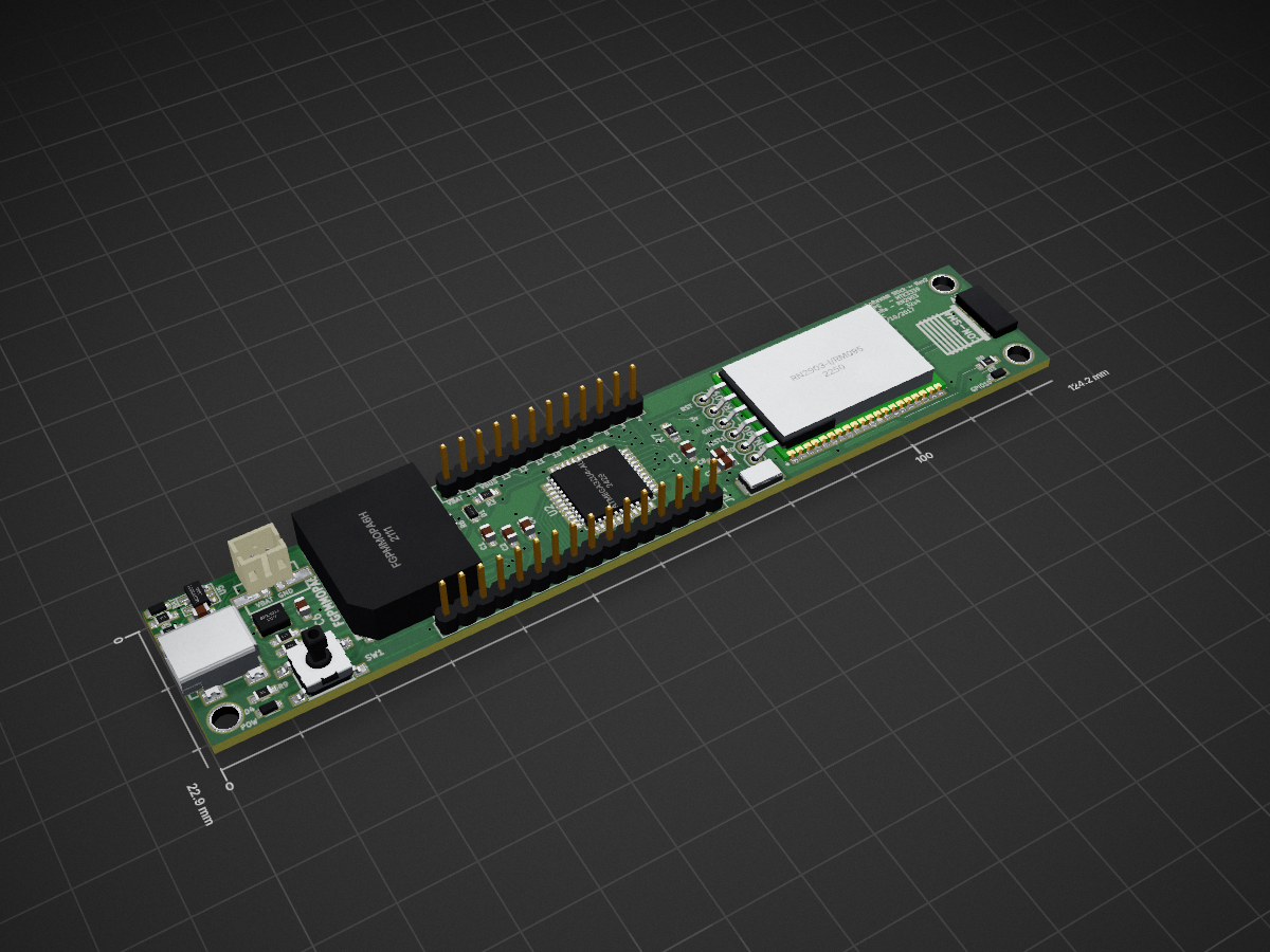
2 layers124.1 × 22.9 mmLoraWAN Stick, the printed circuit board in 3D

Microcontroller + GPS Receiver + LoRaWAN radio

Size
124.1 × 22.9 mm
Copper layers
2
Thickness
1.6 mm
Parts
37
Nets
83
Pads
226
Tracks, vias
638, 115
Pours
1
Routed
Yes
KiCad
KiCad 4
Created
28 Dec 2016
Updated
27 Jan 2017

Overview

LoraWAN Stick is an open-source printed circuit board by lostangles, from the lostangles/LoraWAN-Stick repository on GitHub. It is a 2-layer board of 124.1 × 22.9 mm with 37 parts on 83 nets, routed with 638 tracks and 115 vias.

It is built around the ATMEGA32U4-AU, MCP73831 and SPX3819S. Its parts include 9 resistors, 8 capacitors, 5 ICs, 4 diodes and 2 connectors. It belongs with the radio and wireless and interfaces and adapters boards and the AVR (ATmega, ATtiny) boards of this library.

Main components

3

README

README.md

LoraWAN-Stick

PCB combining Atmega32u4, MTK3339 GPS module, and RN2903 LoraWAN module.

Alt text

Order from OSH Park

Functionality

I wanted to make a single PCB that had some GPIO, communication interfaces, a module to transmit LoraWAN packets, and a way to get current location. The LoraWAN stack is offloaded from the 32u4 and rests in a PIC microcontroller inside the RN2903. This allows a simple interface of simply passing the payload from the 32u4 to the RN2903 without having to worry about the LoraWAN stack inside your project.

The LoraWAN-Stick incorporates the LiPo charging circuitry common to the Adafruit Feather line of dev boards, as well as follows the same pinout for attachment of Adafruit Featherwings. Because both the RN2903 and GPS module use serial communications, serial communications with other nodes may be difficult; the GPS module uses the hardware UART, and communication to the RN2903 uses software serial. From my experience, having multiple software serial interfaces tends to work in unexpected ways, and should probably be avoided without thorough testing.

Pins

Pinout follows Adafruit Feather format as I wanted to be able to add compatability of Adafruit Featherwings to this project. The 32u4 only has a single hardware UART, hard wired to the TX/RX of the GPS module. These pins are broken out on the header.

The RN2903 is controlled by serial, but because the 32u4 has only a single UART, a software serial interface must be used. The RN2903 is hardwired with its RX on pin 5 and TX on pin 10. Reset for the RN2903 is hard wired to pin 6 and should be pulled high when not in reset state. The RN2903 Pickit3 programming header is also broken out to update the firmware on the RN2903 directly.

#uC Info The 32u4-AU microcontroller that I used here comes preconfigured to use the internal oscillator, thus the C7, C8, and XTAL pads can be left empty. When configuring the microcontroller for the first time, it will not show up as a USB device until the bootloader has been flashed to it via ISP. Once the bootloader has been flashed, it should show up as an Adafruit Feather 32u4 under Device Manager, and can be programmed/configured in the same manner as any of the Adafruit 32u4 Feathers.

#Radio Interface The RN2903 by default communicates on 56000 baud. The SoftwareSerial library is more reliable at slower speeds; to set the baudrate in the RN2903, you must send a low signal on the TX line for at least two character lengths, followed by 0x55 at the new baudrate requested. Using the Arduino libraries, this might look like:

text
digitalWrite(10, LOW);
delay(500);
digitalWrite(10, HIGH);
rn2903.begin(9600);
rn2903.write(0x55);

#Fuse Settings The bootloader included configures the 32u4 in 8 MHz in the same configuration as the Adafruit 32u4 Feathers. The uC can be configured to run with an internal oscillator or an external oscillator. If you use the 32u4-AU variant, the built in oscillator can be used in lieu of an external oscillator. The fuse settings to configure the uC as such would be something like:

avrdude -c dragon_isp -p m32u4 -U lfuse:w:0xe2:m -U hfuse:w:0xd8:m -U efuse:w:0xfb:m -U flash:w:Caterina-Feather32u4.hex -v

Bill Of Materials

https://github.com/lostangles/LoraWAN-Stick/blob/master/LoraWAN-Stick.xlsx

Total cost: $52.52

U3 RN2903-I/RM095 RN2903-I_RM095:XCVR_RN2903-I%2fRM095 Microchip U2 ATmega32U4-AU Housings_QFP:TQFP-44_10x10mm_Pitch0.8mm U1 FGPMMOPA6H FGPMMOPA6H:FGPMMOPA6H P1 USB_OTG Connect:USB_Mini-B R1 22 Resistors_SMD:R_0603_HandSoldering R2 22 Resistors_SMD:R_0603_HandSoldering U4 SPX3819 adafruit:adafruit-SOT23-5L R3 100k Resistors_SMD:R_0603_HandSoldering C1 10uF Capacitors_SMD:C_0603_HandSoldering C2 10uF Capacitors_SMD:C_0603_HandSoldering C3 1uF Capacitors_SMD:C_0603_HandSoldering D1 DIODESCH Diodes_SMD:D_0805 CN1 JST_2PIN-SMT adafruit:adafruit-JST-PH-2-SMT C4 1uF Capacitors_SMD:C_0603_HandSoldering SW1 SPST open-project:SW_PUSH_SMD U5 MCP73831 arthurc:SOT23-5 D2 LED-BAT Diodes_SMD:D_0805 R4 1k Resistors_SMD:R_0603_HandSoldering R5 10k Resistors_SMD:R_0603_HandSoldering C5 10uF Capacitors_SMD:C_0603_HandSoldering R6 100k Resistors_SMD:R_0603_HandSoldering R7 100k Resistors_SMD:R_0603_HandSoldering C6 10uF Capacitors_SMD:C_0603_HandSoldering JP3 PINHD-1X12 adafruit:adafruit-1X12 JP1 CONN_01X16 Pin_Headers:Pin_Header_Straight_1x16 JP2 PINHD-1X6 adafruit:adafruit-1X06 ANT1 CON-SMA misc:CON-SMA-EDGE D3 LED-RED Diodes_SMD:D_0805 R8 1k Resistors_SMD:R_0603_HandSoldering D4 LED-POW Diodes_SMD:D_0805 R9 1k Resistors_SMD:R_0603_HandSoldering

TODO

Add ICP header for 32u4

Parts

37
QtyValueFootprintReferences
410uFCapacitors_SMD:C_0603_HandSolderingC1, C2, C5, C6
3100kResistors_SMD:R_0603_HandSolderingR3, R6, R7
31kResistors_SMD:R_0603_HandSolderingR4, R8, R9
21uFCapacitors_SMD:C_0603_HandSolderingC3, C4
222Resistors_SMD:R_0603_HandSolderingR1, R2
2CCapacitors_SMD:C_0603_HandSolderingC7, C8
110kResistors_SMD:R_0603_HandSolderingR5
1ATmega32U4-AUHousings_QFP:TQFP-44_10x10mm_Pitch0.8mmU2
1CON-SMAmisc:CON-SMA-EDGEANT1
1CONN_01X16Pin_Headers:Pin_Header_Straight_1x16JP1
1CRYSTAL_2Crystals:ABM38MHz1
1DIODESCHDiodes_SMD:D_0805D1
1FGPMMOPA6HFGPMMOPA6H:FGPMMOPA6HU1
1JST_2PIN-SMTadafruit:adafruit-JST-PH-2-SMTCN1
1LED-BATDiodes_SMD:D_0805D2
1LED-POWDiodes_SMD:D_0805D4
1LED-REDDiodes_SMD:D_0805D3
1MCP73831arthurc:SOT23-5U5
1PINHD-1X12Pin_Headers:Pin_Header_Straight_1x12JP3
1PINHD-1X6adafruit:adafruit-1X06JP2
1RN2903-I/RM095RN2903-I_RM095:XCVR_RN2903-I%2fRM095U3
1SPSTopen-project:SW_PUSH_SMDSW1
1SPX3819misc:SPX3819U4
1USB_OTGConnect:USB_Mini-BP1

The 34 most common of 37 parts.

Questions

How big is the LoraWAN Stick PCB?

It measures 124.1 × 22.9 mm and has 2 copper layers, 1.6 mm thick.

What parts does the LoraWAN Stick use?

37 parts, built around the ATMEGA32U4-AU, MCP73831 and SPX3819S. The full list of its parts is on this page, with links to each part's symbol and footprint where PCBKit's library has them.

Where can I download the LoraWAN Stick KiCad files?

From the lostangles/LoraWAN-Stick repository on GitHub, at the commit this page was made from: the board is LoraWAN-Stick.kicad_pcb. PCBKit opens the board in the browser, with nothing to install.

Can I use the LoraWAN Stick design in my own project?

Its repository states no licence, so its author keeps all rights: ask lostangles before reusing the design.
Similar boards

  • 2 layers111.9 × 34.6 mmLoraWAN Stick LoraWAN Header Backwards, the printed circuit board in 3D

    LoraWAN Stick LoraWAN Header Backwards

    PCBench/PCBench

    resolution = [0.5, 0.5] pcbfolder = '../PCBs/' pcbnames = ["1Bitsy1bitsy"] iters = 30 env = PCBRoutingEnv(resolution=resolution, pcbfolder=pcbfolder, pcbnames=pcbnames) obs, info = env.reset() for in range(iters): act =…

    31 parts21MIT
  • 2 layers76.2 × 76.2 mmJotter RevC, the printed circuit board in 3D

    Jotter RevC

    SpatialExperienceGroup/jotter

    47 partsMIT
  • 2 layers196 × 104 mmHack fft, the printed circuit board in 3D

    Hack fft

    hack-apollo/hack_spectrum

    a music spectrum use esp32-pico-d4 and ws2812b.

    611 parts28GPL-3.0
  • 2 layers50 × 50 mmBreakout, the printed circuit board in 3D

    Breakout

    skorokithakis/A6-ESP8266-breakout

    A breakout board that includes an ESP8266 and an A6 GSM module, for easily making GSM-enabled applications (mirror)

    38 parts9BSD-2-Clause
  • 2 layers42 × 42 mmMotor, the printed circuit board in 3D

    Motor

    ErnestWang31/CLND1

    Custom Closed-Loop Driver for Stepper Motors

    52 parts2MIT
  • 2 layers24 × 36 mmLoRaModem, the printed circuit board in 3D

    LoRaModem

    wangyeee/OpenHardware

    Collections of hardware design related to my drone project.

    48 parts10BSD-3-Clause
  • 2 layers97.1 × 97.1 mmESP32 IMU Module V1.1, the printed circuit board in 3D

    ESP32 IMU Module V1.1

    shaun-lloyd/dev-ardupilot-obal

    ArduPi is an open hardware Raspberry Pi hat to run Ardupilot.

    87 parts2CC0-1.0
  • 2 layersCopycat, the printed circuit board in 3D

    Copycat

    FE3C61AD329B/RGT6

    A minimal system runs MicroPython using STM32F405RGT6

    37 parts