4 layers102 × 49 mm
CURSO PCB DRONE
ArduProject/PCB_DRONE_C8
En este repositorio encontrareis los archivos de fabricación y las listas de montaje del PCB con STM32F103C8 que hemos visto en el curso.
153 parts1MIT

 llatva/hzbugger
Hzbugger, a Black Magic Probe compatible SWD/debugger tool
Hzbugger is an open-source printed circuit board by llatva, from the llatva/hzbugger repository on GitHub, published under the CERN-OHL-S-2.0 licence. It is a 2-layer board of 54.5 × 31.2 mm with 62 parts on 66 nets, routed with 511 tracks and 222 vias.
It is built around the STM32F103C8T6, AMS1117-3.3 and SRV05-4, with the SS14 among its other parts. Its parts include 23 resistors, 15 capacitors, 8 diodes, 4 ICs and 3 connectors. It belongs with the interfaces and adapters and sensors and measurement boards and the STM32 boards of this library.


Hzbugger is an STM32F103C8T6-based Black Magic Probe compatible debugger by Lasse OH3HZB.
Bottom side silkscreen created using AI tools (intended for black PCB as in pictures below).
Basic functionality works out-of-box with BMP bluepill image. Extra LEDs and AUX header requires fw customization. See BlackMagic Probe adaptation guide for firmware-porting and usage details.
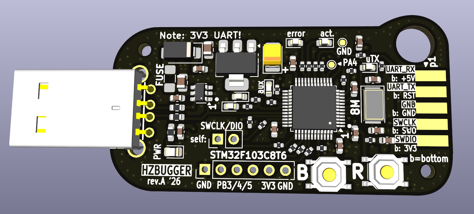
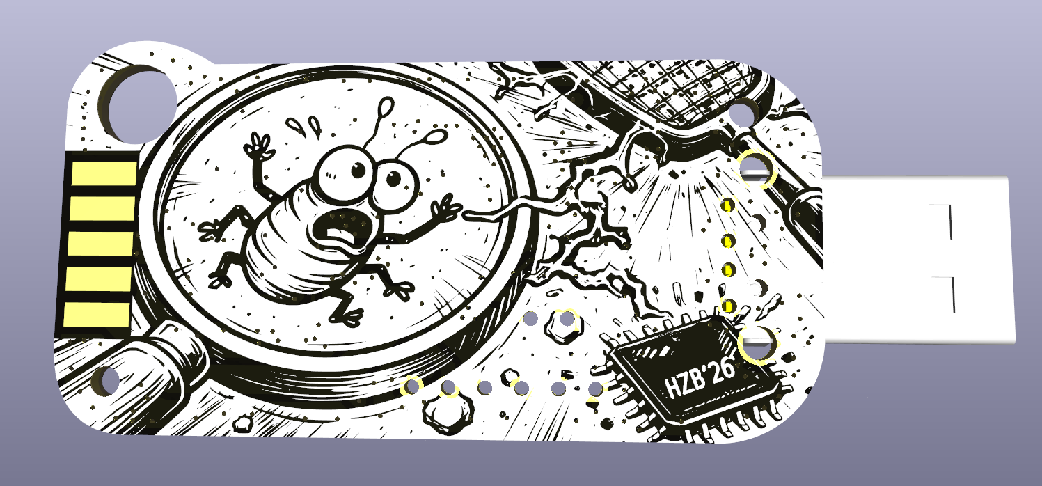
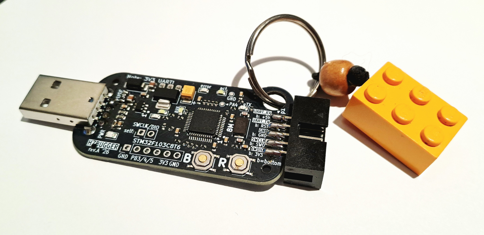
The device should enumerate as /dev/ttyACM0 and /dev/ttyACM1 (on Linux).
Build the application so that the output includes an ELF file containing debug information. For example:
build/my_application.elfThe ELF file is used both for programming the target and for debugging. Start GDB from the shell:
arm-none-eabi-gdb build/my_application.elfThen run the following commands inside GDB:
target extended-remote /dev/ttyACM1
monitor erase_mass
load
monitor resetarm-none-eabi-gdbThe firmware should be built with debug information enabled, for example:
-gFor development builds, it is also useful to disable compiler optimization:
-O0This makes source-level debugging easier.
Create the following file in your project:
.vscode/launch.jsonAdd debug configuration:
{
    "version": "0.2.0",
    "configurations": [
        {
            "name": "Debug with Black Magic Probe",
            "type": "cortex-debug",
            "request": "launch",
            "servertype": "bmp",
            "executable": "${workspaceFolder}/build/my_application.elf",
            "device": "YOUR_MCU",
            "cwd": "${workspaceFolder}",
            "runToEntryPoint": "main"
        }
    ]
}
Replace YOUR_MCU with the name of your target MCU.
Also update the executable path if your ELF file is located somewhere else.
Connect Hzbugger and start the debugger in VS Code using F5 button.
VS Code will use GDB to connect to the Hzbugger and start a debug session.
You can then use the normal VS Code debugging features:
F10F11Shift+F11F5arm-none-eabi-gdb --versionls /dev/ttyACMarm-none-eabi-gdb build/my_application.elftarget extended-remote /dev/ttyACM1monitor erase_massloadmonitor reset(Hzbugger acts as a GDB server itself so you do not need to start a separate (e.g. OpenOCD) GDB server)
CERN-OHL-S (strongly reciprocal), see LICENSE.txt for details.
| Qty | Value | Footprint | References |
|---|---|---|---|
| 10 | 100n | Capacitor_SMD:C_0603_1608Metric | C2, C3, C5, C7, C9, C10, C14, C15, C16, C17 |
| 10 | 22R | Resistor_SMD:R_0402_1005Metric | R1, R2, R9, R10, R14, R15, R16, R17, R22, R23 |
| 6 | 1k5 | Resistor_SMD:R_0402_1005Metric | R3, R13, R18, R19, R20, R21 |
| 3 | 10k | Resistor_SMD:R_0402_1005Metric | R7, R8, R12 |
| 3 | LED1 | LED_SMD:LED_0603_1608Metric | D3, D5, D7 |
| 2 | 10u | Capacitor_SMD:C_0805_2012Metric | C4, C6 |
| 2 | 22R | Resistor_SMD:R_0603_1608Metric | R4, R5 |
| 2 | 22p | Capacitor_SMD:C_0603_1608Metric | C11, C12 |
| 2 | MountingHole | MountingHole:MountingHole_2.1mm | H1, H3 |
| 1 | 100u | Capacitor_Tantalum_SMD:CP_EIA-3528-21_Kemet-B_Pad1.50x2.35mm_HandSolder | C8 |
| 1 | 1A | Fuse:Fuse_1206_3216Metric_Pad1.42x1.75mm_HandSolder | F1 |
| 1 | 1k5 | Resistor_SMD:R_0603_1608Metric_Pad0.98x0.95mm_HandSolder | R6 |
| 1 | 1k5 | Resistor_SMD:R_0402_1005Metric_Pad0.72x0.64mm_HandSolder | R11 |
| 1 | 8M | Crystal:Crystal_SMD_5032-2Pin_5.0x3.2mm | Y1 |
| 1 | ACT_LED | LED_SMD:LED_0603_1608Metric | D8 |
| 1 | AMS1117-3.3 | Package_TO_SOT_SMD:SOT-223-3_TabPin2 | U3 |
| 1 | BOOT0_SW | hzbugger:SW-SMD_4P-L5.1-W5.1-P3.70-LS6.5-TL_H1.5 | SW2 |
| 1 | ERR_LED | LED_SMD:LED_0603_1608Metric | D6 |
| 1 | GPIO | Connector_PinHeader_2.54mm:PinHeader_1x06_P2.54mm_Vertical | J6 |
| 1 | HX AM 90D | hzbugger:USB-A-TH_HANXIA_HXAM90D | U4 |
| 1 | IDC | hzbugger:SMD-pcbend-IDC-Header_2x05_P2.54mm | J2 |
| 1 | LED2 | LED_SMD:LED_0603_1608Metric | D4 |
| 1 | LOGO | LOGO | G*** |
| 1 | PWR_LED | LED_SMD:LED_0805_2012Metric | D1 |
| 1 | RESET_SW | hzbugger:SW-SMD_4P-L5.1-W5.1-P3.70-LS6.5-TL_H1.5 | SW1 |
| 1 | SELF_SWD | Connector_PinHeader_2.54mm:PinHeader_1x02_P2.54mm_Vertical | J1 |
| 1 | SRV05-4 | Package_TO_SOT_SMD:SOT-23-6 | U2 |
| 1 | SS14 | Diode_SMD:D_SMA | D2 |
| 1 | STM32F103C8T6 | Package_QFP:LQFP-48_7x7mm_P0.5mm | U1 |
| 1 | TPA14 | TestPoint:TestPoint_Pad_D1.0mm | TP1 |
| 1 | TPG1 | TestPoint:TestPoint_Pad_D1.0mm | TP2 |
It measures 54.5 × 31.2 mm and has 2 copper layers, 1.6 mm thick.
62 parts, built around the STM32F103C8T6, AMS1117-3.3, SRV05-4 and SS14. The full list of its parts is on this page, with links to each part's symbol and footprint where PCBKit's library has them.
From the llatva/hzbugger repository on GitHub, at the commit this page was made from: the board is hzbugger.kicad_pcb and its schematic hzbugger.kicad_sch. PCBKit opens the board in the browser, with nothing to install.
Its repository publishes it under the CERN-OHL-S-2.0 licence: you may reuse it on that licence's terms (keep the author's notice, and for a copyleft licence share your changes alike).
ArduProject/PCB_DRONE_C8
En este repositorio encontrareis los archivos de fabricación y las listas de montaje del PCB con STM32F103C8 que hemos visto en el curso.

hackclub/OnBoard
💡 Join 1,000 teenagers and make your first PCB with a $100 grant!


RaduAndre/DeskMixer
DeskMixer is a software that allows control of application volumes with real sliders, and action mapping on buttons using arduino like platforms. The project was inspired originally by deej.

yukselturkomer/50w-buck-converter-stm32
Bu proje, STM32 mikrodenetleyici kullanılarak geliştirilmiş 50W kapasiteli bir Buck (Düşürücü) Konvertör sistemini ve bu sistemin kontrolünü sağlayan Nextion HMI (İnsan-Makine Arayüzü) tasarımını içermektedir.


mornepousse/Niphargus
Niphargus — a slim, indestructible wireless split keyboard. ESP32 + nRF24, wired fallback, and an emergency kit hidden behind the USB port. The successor to the Rouge-Gorge.
