2 layers84.5 × 128.5 mm
Schraeg
barnabywalters/Schraeg
An 8HP eurorack multimode filter module based on the Bastl Cinnamon
116 parts43CC-BY-SA-4.0

 even-notodd/USB-DALI4
USB-DALI interface converter
USB DALI is an open-source printed circuit board by even-notodd, from the even-notodd/USB-DALI repository on GitHub. It is a 2-layer board of 71.3 × 25.4 mm with 43 parts on 60 nets, routed with 264 tracks and 16 vias.
It is built around the STM32F103C8T6, MT3608 and AMS1117-3.3, with the SS14, BCX56 and MB2S among its other parts. Its parts include 15 resistors, 9 capacitors, 6 diodes, 5 ICs and 5 connectors. It belongs with the STM32 boards of this library.


USB-DALI adapter. The device works as a gateway allowing sending data via USB VCP (USB Virtual COM Port) to DALI bus and reading data from DALI bus via Modbus RTU protocol. The device can be operated via standard Modbus RTU commands set. Data exchange examples can be found in the repo. Hardware includes DALI bus power supply. Software includes C# sample of sending basic DALI commands including DALI configuration and a simple GUI.
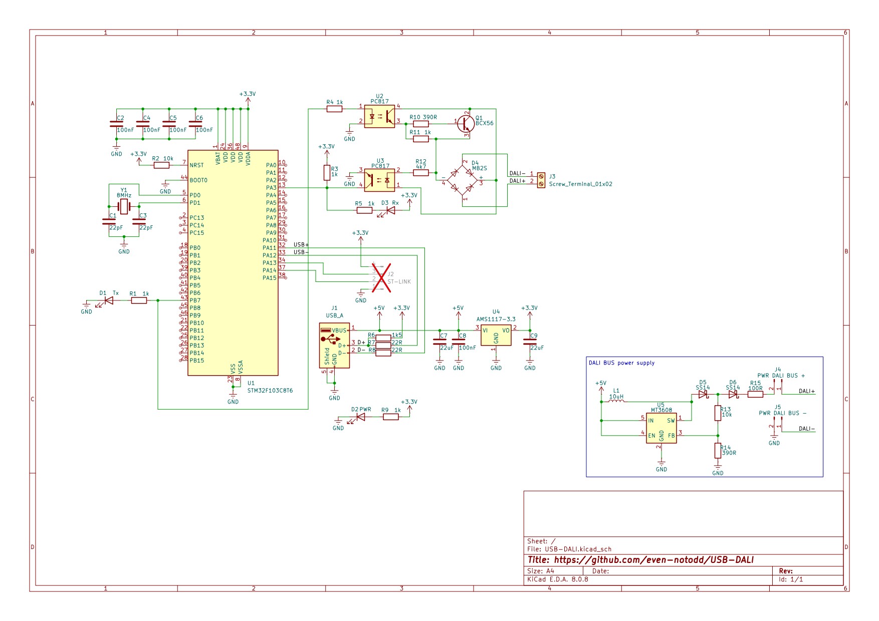
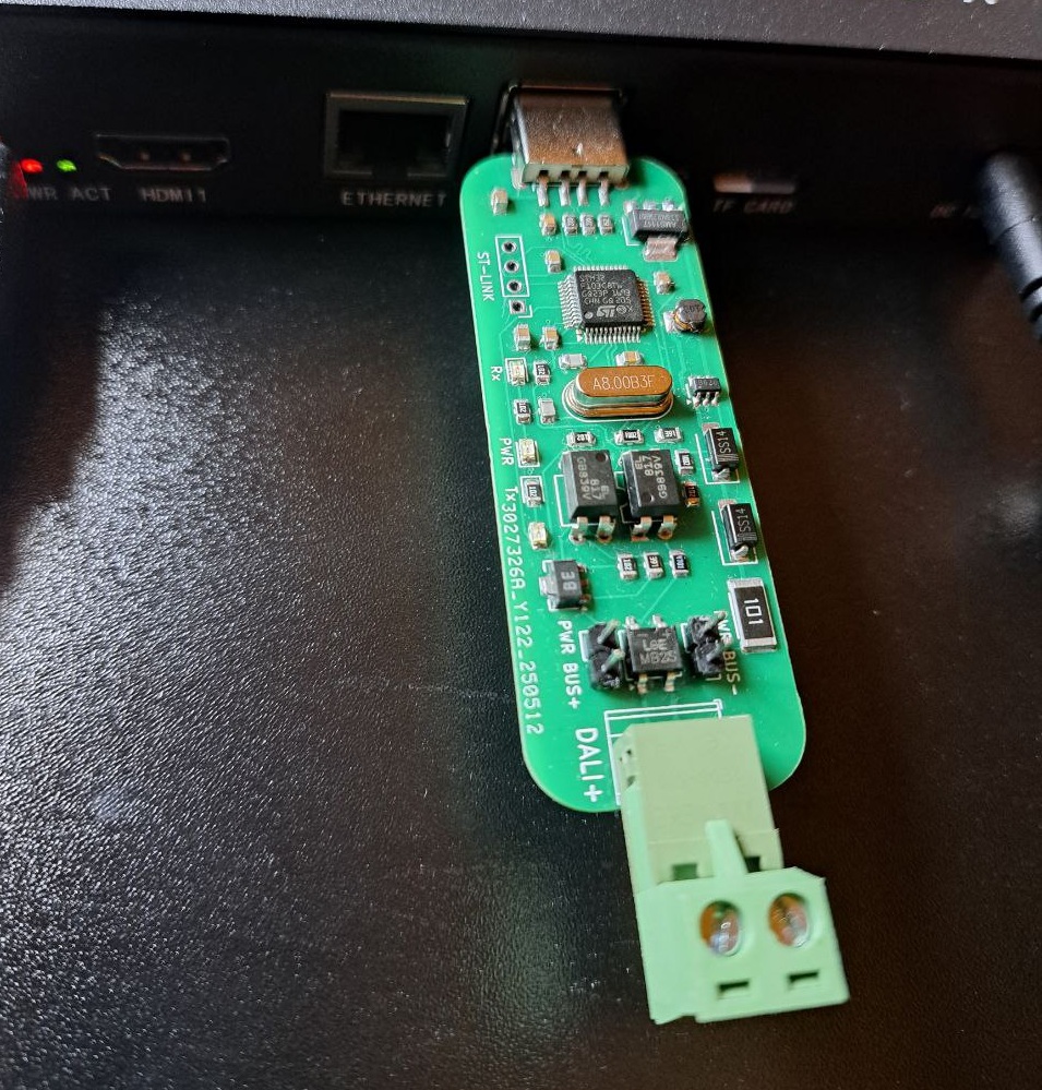
This design has been tested before and successfully used in several systems. The device is built around popular STM32F103C8T6 using MCUs USB. The DALI "physical layer" is build with a few discrete components without any special transceiver. The hardware implementation also includes DALI bus power supply which simplifies its usage in building hardware setups through design & development process. Nevertheless we don't recommend (!) using it as bus power supply in any permanent installations.
The module can work with DALI line powered from external DALI power supply or powered from own built-in 16V 160mA converter (powered from USB). If you are planning to use external power supply it’s important to open 2 jumpers on the board before connection the module to DALI network and USB. Do not use 2 power supplies (external and internal) at the same time! While working with both of jumpers open (external power supply), the module provides galvanic isolation between USB and DALI, but when powered from built-in power supply, DALI line has not galvanic isolation from USB. Being connected to USB, the module can be found in operating system as virtual COM port. It’s important to admit, that after connection to that port from the software, it takes MCU some time to create stable connection so it’s recommended to keep 3-5 seconds pause between connection and start of data exchange.
The software is a demo GUI providing simple access to direct and indirect commands in DALI network (like broadcasting of brightness, working with individual addresses etc). Visual Studio Community Edition can be used to build or modify.
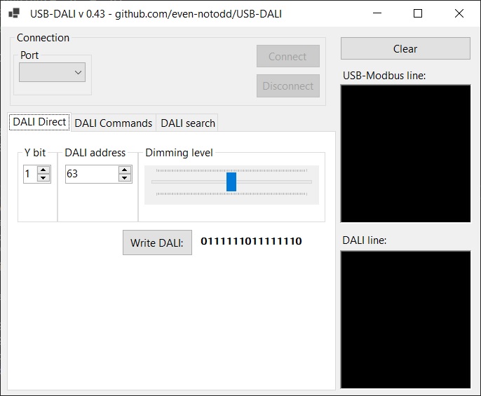
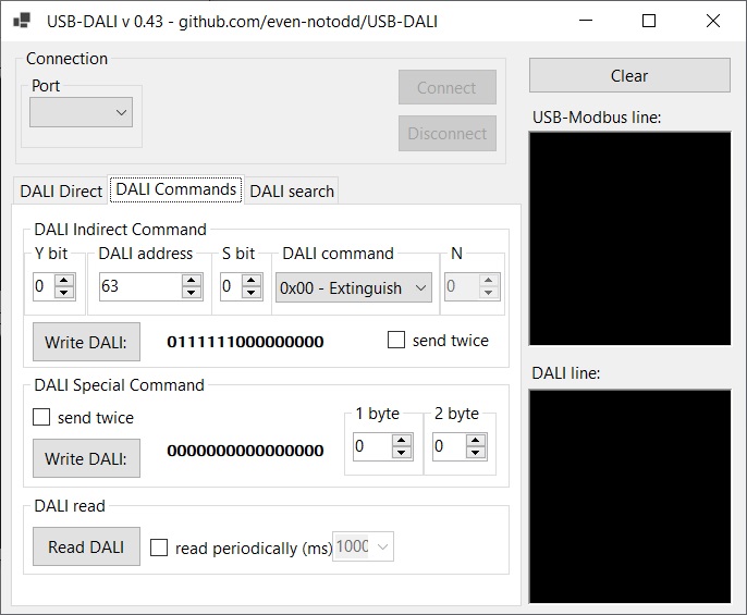
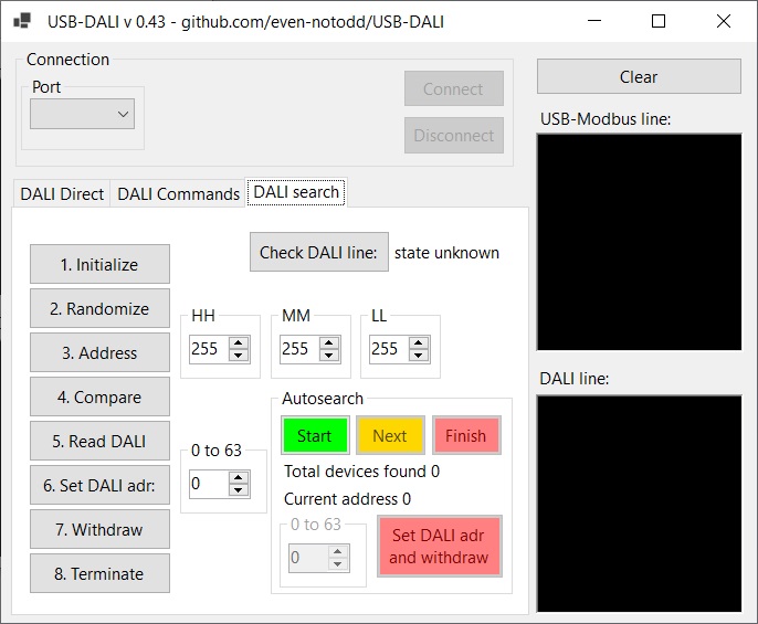
The device works as VCP (Virtual COM Port). When using with Linux - no drivers required. For Windows - VCP driver from ST Microelectronics should be used. The Modbus address of the USB-DALI module is 0x01 (not changeable). As far as there is no possibility to connect other devices to the same USB VCP, it will be always the only device in created Modbus network.
Firmware file can be found in corresponding sub-folder and can be flashed to MCU with ST-Link (optionally J-Link).
For protocol description and examples look inside
See the for details.
| Qty | Value | Footprint | References |
|---|---|---|---|
| 6 | 1k | Resistor_SMD:R_0805_2012Metric | R1, R3, R4, R5, R9, R11 |
| 5 | 100nF | Capacitor_SMD:C_0805_2012Metric | C2, C4, C5, C6, C8 |
| 2 | 10k | Resistor_SMD:R_0805_2012Metric | R2, R13 |
| 2 | 22R | Resistor_SMD:R_0805_2012Metric | R7, R8 |
| 2 | 22pF | Capacitor_SMD:C_0805_2012Metric | C1, C3 |
| 2 | 22uF | Capacitor_SMD:C_0805_2012Metric | C7, C9 |
| 2 | 390R | Resistor_SMD:R_0805_2012Metric | R10, R14 |
| 2 | PC817 | Package_DIP:DIP-4_W7.62mm | U2, U3 |
| 2 | SS14 | Diode_SMD:D_SMA | D5, D6 |
| 1 | 100R | Resistor_SMD:R_2512_6332Metric | R15 |
| 1 | 10uH | Inductor_SMD:L_1210_3225Metric | L1 |
| 1 | 1k5 | Resistor_SMD:R_0805_2012Metric | R6 |
| 1 | 4k7 | Resistor_SMD:R_0805_2012Metric | R12 |
| 1 | 8MHz | Crystal:Crystal_HC49-U_Vertical | Y1 |
| 1 | AMS1117-3.3 | Package_TO_SOT_SMD:SOT-223-3_TabPin2 | U4 |
| 1 | BCX56 | Package_TO_SOT_SMD:SOT-89-3 | Q1 |
| 1 | MB2S | Package_TO_SOT_SMD:TO-269AA | D4 |
| 1 | MT3608 | Package_TO_SOT_SMD:SOT-23-6 | U5 |
| 1 | PWR | LED_SMD:LED_0805_2012Metric | D2 |
| 1 | PWR BUS+ | Connector_PinHeader_2.54mm:PinHeader_1x02_P2.54mm_Vertical | J4 |
| 1 | PWR BUS- | Connector_PinHeader_2.54mm:PinHeader_1x02_P2.54mm_Vertical | J5 |
| 1 | Rx | LED_SMD:LED_0805_2012Metric | D3 |
| 1 | ST-LINK | Connector_PinHeader_2.54mm:PinHeader_1x04_P2.54mm_Vertical | J2 |
| 1 | STM32F103C8T6 | Package_QFP:LQFP-48_7x7mm_P0.5mm | U1 |
| 1 | Screw_Terminal_01x02 | TerminalBlock_Phoenix:TerminalBlock_Phoenix_MKDS-1,5-2-5.08_1x02_P5.08mm_Horizontal | J3 |
| 1 | Tx | LED_SMD:LED_0805_2012Metric | D1 |
| 1 | USB_A | Connector_USB:USB_A_CNCTech_1001-011-01101_Horizontal | J1 |
It measures 71.3 × 25.4 mm and has 2 copper layers, 1.6 mm thick.
43 parts, built around the STM32F103C8T6, MT3608, AMS1117-3.3 and SS14. The full list of its parts is on this page, with links to each part's symbol and footprint where PCBKit's library has them.
From the even-notodd/USB-DALI repository on GitHub, at the commit this page was made from: the board is Hardware/USB-DALI.kicad_pcb and its schematic Hardware/USB-DALI.kicad_sch. PCBKit opens the board in the browser, with nothing to install.
Its repository states no licence, so its author keeps all rights: ask even-notodd before reusing the design.
barnabywalters/Schraeg
An 8HP eurorack multimode filter module based on the Bastl Cinnamon

transportkollektiv/feuchtraumabzweigdose
A custom GPS Tracker with LoRaWAN/TTN intended for use on a bicycle

skunkforce/edgy_boards_legacy
small mostly single chip design bits with put_on_edge connectors


RocketScientist26/Quadruped-Hardware
Main, Battery protection and Servo PCBs for Quadruped robot

