Skip to the content
PCBKitNew board
4 layers99.6 × 99.9 mmRailclock, the printed circuit board in 3D

This PCB exposes 11 GPIOs via JST connectors for sensors and actuators. It can run without an external 5V supply by using an on-board battery charger and a boost converter to create a 12V rail for motors and…

Size
99.6 × 99.9 mm
Copper layers
4
Thickness
1.6 mm
Parts
172
Nets
104
Pads
601
Tracks, vias
1,175, 321
Pours
5
Routed
Yes
KiCad
KiCad 10.0 (file 20260206)
Created
27 Jun 2025
Updated
15 Sep 2026

Overview

Railclock is an open-source printed circuit board by L0czek, from the L0czek/railclock repository on GitHub. It is a 4-layer board of 99.6 × 99.9 mm with 172 parts on 104 nets, routed with 1,175 tracks and 321 vias.

It is built around the ESP32-C6-WROOM-1-N8, DRV8870DDA and MCP4728-E/UN, with the BTS5012SDA, BQ25895RTW and PCF8574RGTR(UMW) among its other parts. Its parts include 68 resistors, 35 capacitors, 21 diodes, 16 connectors and 15 ICs. It belongs with the power boards and the ESP32 and RISC-V boards of this library.

Main components

7

README

README.md

ESP32 Mainboard (Railclock-derived)

A general-purpose ESP32-C6 module mainboard originally created for the Railclock project and redesigned as a generic controller and motor-power board.

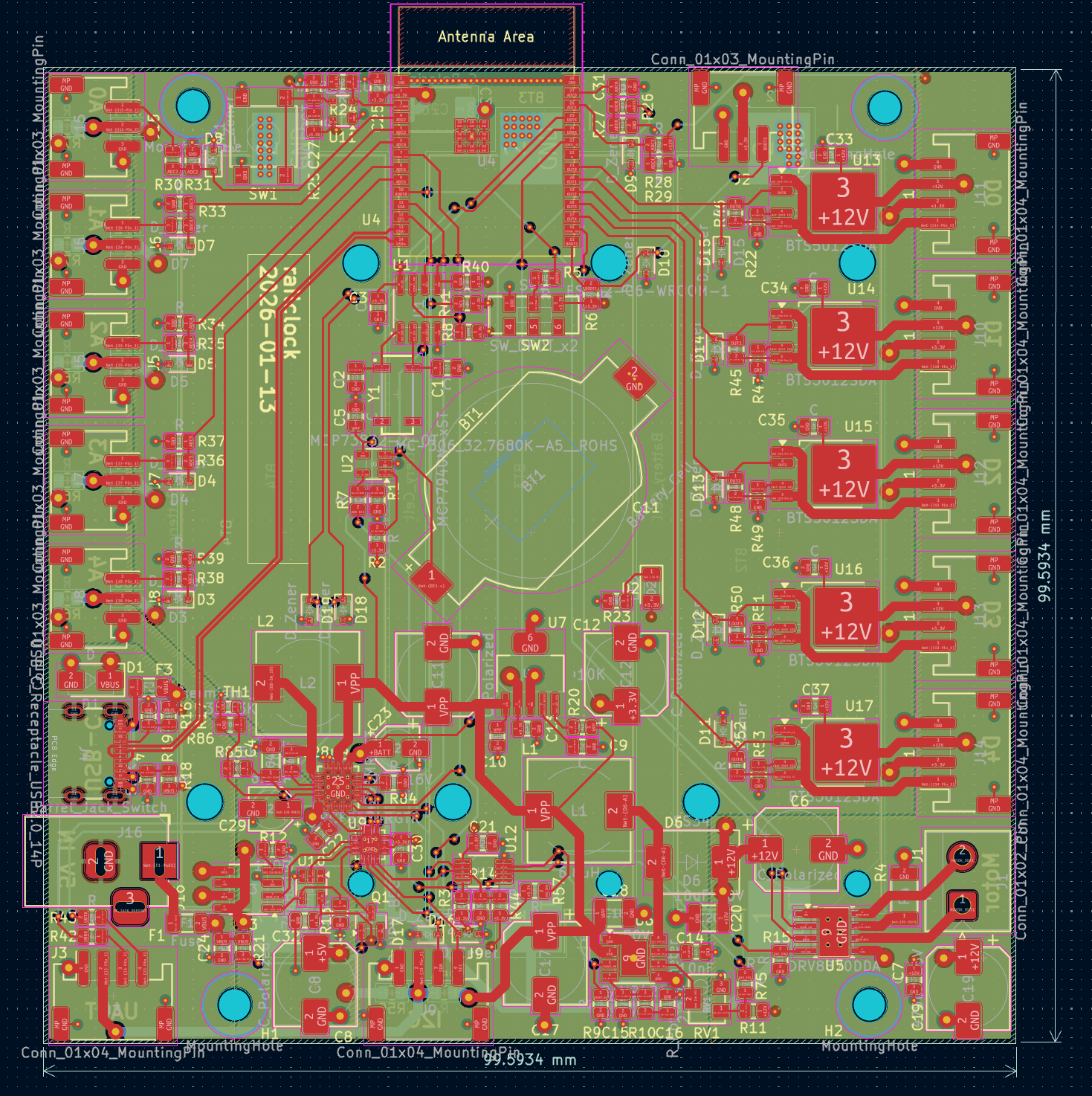
PCB top view

This PCB exposes 11 GPIOs via JST connectors for sensors and actuators. It can run without an external 5V supply by using an on-board battery charger and a boost converter to create a 12V rail for motors and higher-power peripherals.

Key Features

  • 11 accessible GPIOs on JST connectors (5 ADC-capable ports on the left, 5 digital/drive outputs on the right).
  • Left side ports: ADC-capable pins and a selectable 5V supply (powered by on-board 5V regulator/charger when available).
  • Right side ports: digitally-driven output stage able to source up to 12V and ~800 mA (per port design limits depend on load and thermal conditions).
  • On-board power management:
    • BQ24296M battery charger to accept battery power and produce the 5V line when no external USB is present.
    • PAM2421 boost converter to generate the 12V rail from the battery/5V bus.
  • Motor driver: DRV8870 used to drive DC motors from the 12V rail.
  • RTC clock MCP7940n with separate battery.

Hardware Overview

  • Connectors:
    • Left JST ports: ADC-capable pins. Expect up to 5V on these when the 5V supply is enabled — do not exceed 5V on ADC inputs.
    • Right JST ports: digital outputs with high-side/outstage to provide up to 12V for actuators.
  • Power flow:
    • Primary charge/power management by the BQ24296M allows operation from a Li-ion battery without external 5V.
    • The PAM2421 boost converter takes the available rail and creates the 12V bus used by the outputs and motor driver.
  • Motor driver:
    • DRV8870 drives DC motors using the 12V rail; follow the datasheet for current-limiting and heat-sinking requirements.

Firmware

Firmware for this board is written in Rust and maintained in a separate repository: https://github.com/L0czek/esp32-mainboard

Parts

172
QtyValueFootprintReferences
61RResistor_SMD:R_0805_2012MetricR1, R2, R3, R11, R14, R15, R17, R18, R22, R23, R24, R25, R26, R27, R28, R29 +45
18CCapacitor_SMD:C_0805_2012MetricC1, C2, C3, C5, C10, C13, C21, C25, C27, C30, C31, C33, C34, C35, C36, C37 +2
16D_ZenerDiode_SMD:D_SOD-323D3, D4, D5, D7, D8, D9, D10, D11, D12, D13, D14, D15, D16, D17, D18, D19
7Conn_01x04_MountingPinConnector_JST:JST_PH_S4B-PH-SM4-TB_1x04-1MP_P2.00mm_HorizontalJ3, J9, J10, J11, J12, J13, J14
6Conn_01x03_MountingPinConnector_JST:JST_PH_S3B-PH-SM4-TB_1x03-1MP_P2.00mm_HorizontalJ2, J5, J6, J7, J8, J15
5BTS5012SDAPackage_TO_SOT_SMD:TO-252-4U13, U14, U15, U16, U17
4C_PolarizedCapacitor_SMD:CP_Elec_8x10C6, C11, C12, C22
4MountingHoleMountingHole:MountingHole_3.2mm_M3H1, H2, H3, H4
3Battery_CellBattery:BatteryHolder_Keystone_1042_1x18650BT2, BT3, BT4
210kResistor_SMD:R_0805_2012MetricR61, R62
210uF 50VCapacitor_SMD:C_1210_3225MetricC18, C20
2470uF 25VCapacitor_SMD:CP_Elec_8x10C17, C19
25.1KResistor_SMD:R_0805_2012MetricR16, R19
2FuseFuse:Fuse_1206_3216MetricF1, F3
1100nFCapacitor_SMD:C_0805_2012MetricC38
110KResistor_SMD:R_0805_2012MetricR20
110nFCapacitor_SMD:C_0805_2012MetricC14
110uFCapacitor_SMD:C_0805_2012MetricC40
12.2nFCapacitor_SMD:C_0805_2012MetricC16
12.2uFInductor_SMD:L_Bourns_SRP1038C_10.0x10.0mmL3
122uF 16VCapacitor_SMD:CP_Elec_4x5.3C23
14.7uFCapacitor_SMD:C_0805_2012MetricC39
147pFCapacitor_SMD:C_0805_2012MetricC15
150uFCapacitor_SMD:C_0805_2012MetricC41
151KResistor_SMD:R_0805_2012MetricR10
16.8uHInductor_SMD:L_10.4x10.4_H4.8L1
1BQ25895RTWPackage_DFN_QFN:Texas_RTW_WQFN-24-1EP_4x4mm_P0.5mm_EP2.7x2.7mm_ThermalViasU18
1Barrel_Jack_SwitchConnector_BarrelJack:BarrelJack_HorizontalJ16
1Battery_CellBattery:BatteryHolder_Renata_SMTU2032-LF_1x2032BT1
1C_PolarizedCapacitor_Tantalum_SMD:CP_EIA-7343-31_Kemet-DC26
1Conn_01x02_PinConnector_JST:JST_NV_B02P-NV_1x02_P5.00mm_VerticalJ1
1DDiode_SMD:D_SMAD1
1DRV8870DDAPackage_SO:Texas_HTSOP-8-1EP_3.9x4.9mm_P1.27mm_EP2.95x4.9mm_Mask2.4x3.1mm_ThermalViasU5
1ESP32-C6-WROOM-1PCM_Espressif:ESP32-C6-WROOM-1U4
1LEDLED_SMD:LED_0805_2012MetricD21
1LEDLED_SMD:LED_1206_3216MetricD2
1MAX811TEUS-TPackage_TO_SOT_SMD:SOT-143U11
1MC-306_32.7680K-A5__ROHSth:OSCL550P800X320X254-4NY1
1MCP4728Package_SO:MSOP-10_3x3mm_P0.5mmU12
1MCP73832-2-OTPackage_TO_SOT_SMD:SOT-23-5U2
1MCP7940N-xSTPackage_SO:SOIC-8_3.9x4.9mm_P1.27mmU1
1PAM2421Package_SO:Diodes_SO-8EPU6
1PCF8574RGTRth:QFN50P300X300X100-17NU9
1RResistor_SMD:R_2010_5025MetricR4
1R_PotentiometerPotentiometer_SMD:Potentiometer_Bourns_3214W_VerticalRV1
1SS14-DCDiode_SMD:D_SMAD22
1SS34Diode_SMD:D_SMCD6
1SW_DPDT_x2Button_Switch_SMD:SW_DPDT_CK_JS202011JCQNSW2
1SW_SPSTButton_Switch_SMD:Panasonic_EVQPUL_EVQPUCSW3
1SW_SPSTButton_Switch_SMD:SW_SPST_B3S-1000SW1
1USB_C_Receptacle_USB2.0_14PConnector_USB:USB_C_Receptacle_GCT_USB4105-xx-A_16P_TopMnt_HorizontalJ4
1~Package_TO_SOT_SMD:SOT-223-6U7

Questions

How big is the Railclock PCB?

It measures 99.6 × 99.9 mm and has 4 copper layers, 1.6 mm thick.

What parts does the Railclock use?

172 parts, built around the ESP32-C6-WROOM-1-N8, DRV8870DDA, MCP4728-E/UN and BTS5012SDA. The full list of its parts is on this page, with links to each part's symbol and footprint where PCBKit's library has them.

Where can I download the Railclock KiCad files?

From the L0czek/railclock repository on GitHub, at the commit this page was made from: the board is railclock.kicad_pcb and its schematic railclock.kicad_sch. PCBKit opens the board in the browser, with nothing to install.

Can I use the Railclock design in my own project?

Its repository states no licence, so its author keeps all rights: ask L0czek before reusing the design.

Similar boards

  • 2 layers99.1 × 99.1 mmConnector test stand, the printed circuit board in 3D

    Connector test stand

    L0czek/rakieta

    The starter board provides the ignition impulse to fire the engine. It includes an I2C IO expander and an 8-channel digital comparator to require a correct safety byte/address to be present before firing.

    86 parts
  • 2 layers52 × 45 mmGeneralNode, the printed circuit board in 3D

    GeneralNode

    SanchakGarg/Hexagon-generator

    25 parts
  • 4 layers114.9 × 129.9 mmTanmatsu, the printed circuit board in 3D

    Tanmatsu

    Nicolai-Electronics/tanmatsu-hardware

    Hardware design of the Tanmatsu mainboard

    372 parts9CERN-OHL-P-2.0
  • 2 layers78 × 103 mmEmbedded.old, the printed circuit board in 3D

    Embedded.old

    borisg912/3DNA

    This project creates a flat cylindrical DNA model with: - Magnetic DNA bases with color-coded NeoPixel LEDs and unique resistor values for identification - Interactive base pairing game that validates correct DNA base…

    121 parts2GPL-3.0
  • 4 layers114.9 × 129.9 mmWhy2025, the printed circuit board in 3D

    Why2025

    ranzbak/why2025-hardware

    Hardware design files for the WHY2025 badge

    384 parts1
  • 2 layers47.9 × 92.3 mmLesonar2 tx hardware, the printed circuit board in 3D

    Lesonar2 tx hardware

    tornyol/lesonar2

    Ultrasonic phased array sonar

    70 parts113AGPL-3.0
  • 4 layers90 × 100 mmPump board, the printed circuit board in 3D

    Pump board

    TrendBit/SMBR-hardware

    Design file for SMBR hardware modules in KiCAD.

    204 partsGPL-3.0