2 layers65 × 56 mm

 koolcat6666/Engine-Simulator-2.0
Engine simulator for ECU testing based on ESP32-32U DevKitC. The system connects to the ECU through the standard Speeduino 40-pin IDC connector and generates signals to simulate real engine operation.
Engine Simulator-2.0 is an open-source printed circuit board by koolcat6666, from the koolcat6666/Engine-Simulator-2.0 repository on GitHub, published under the MIT licence. It is a 2-layer board of 100 × 100 mm with 62 parts on 91 nets, routed with 682 tracks and 18 vias.
It is built around the CD4050BE, 74AHCT125D and ESP32-DEVKITC-VE, with the R-78E5.0-1.0, TLV2372IP and BZX55C3V6-TR among its other parts. Its parts include 17 resistors, 12 connectors, 7 capacitors, 6 ICs and 1 diode. It belongs with the ESP32 boards of this library.


Engine simulator for ECU testing based on the Speeduino V0.4 and the ESP32-32U DevKitC.
The system connects to the ECU through the standard Speeduino 40-pin IDC connector and generates signals to simulate real engine operation.
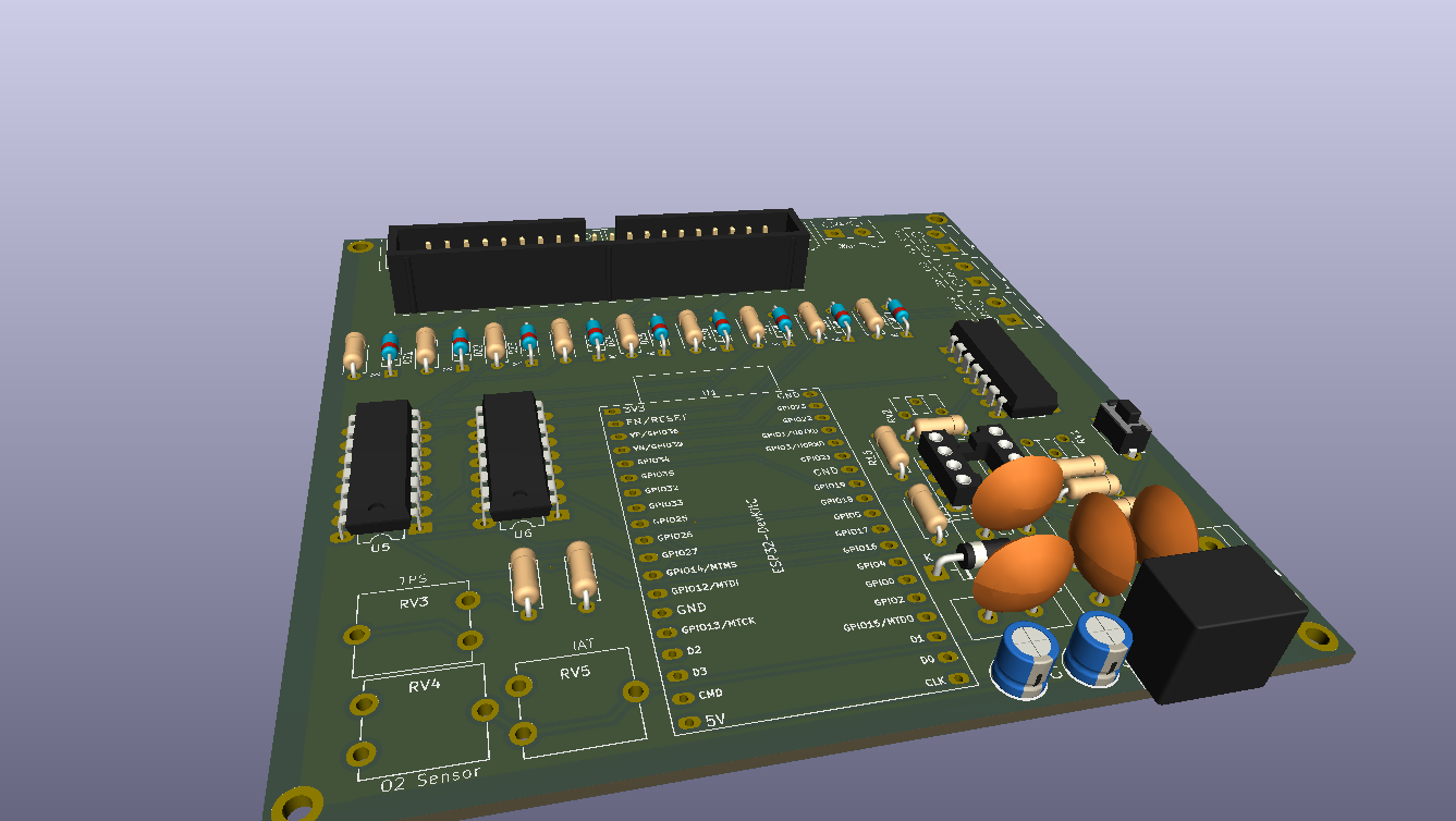
| Signal | ESP32 Pin | To Speeduino | Method |
|---|---|---|---|
| Crank Trigger | GPIO 12 | IDC Pin 25 | Square wave via hardware timer and 3.3V-to-5V level shifter |
| Cam 1 Trigger | GPIO 13 | IDC Pin 24 | Square wave via hardware timer and 3.3V-to-5V level shifter |
| Cam 2 Trigger | GPIO 14 | IDC Pin 24 (optional) | Square wave via hardware timer and 3.3V-to-5V level shifter |
| CLT (Coolant Temperature) | GPIO 26 (DAC2) | IDC Pin 19 | Analog voltage 0–3.3V, amplified to 0–5V |
| MAP (Pressure) | GPIO 25 (DAC1) | IDC Pin 11 | Analog voltage 0–3.3V, amplified to 0–5V |
| Signal | Speeduino Pin | Notes |
|---|---|---|
| TPS (Throttle Position Sensor) | IDC Pin 22 | 5V potentiometer, wiper/common connected to ESP32 ADC (GPIO 34) through a voltage divider |
| IAT (Intake Air Temperature) | IDC Pin 20 | Potentiometer connected directly to Speeduino |
| O2 (Oxygen Sensor) | IDC Pin 21 | Potentiometer connected directly to Speeduino |
| Signal | ESP32 Pin | From Speeduino | Notes |
|---|---|---|---|
| Fan Feedback | GPIO 27 | IDC Pin 15 | Fan status (0V = ON), 5V-to-3.3V voltage divider |
Speeduino outputs such as injectors, ignition/coils, fan, idle, VVT, boost, and fuel pump are read by the ESP32 through CD4050BE buffers for timing calculation (Phase 2).
EngineSimulator2.0, password 1234567890, IP 192.168.254.1, responsive dashboard at /, allows selecting one of 64 trigger patterns and persists the setting to NVS memory/setup page and persisted to NVSWhen the engine is started (physical Start/Stop button or /api/start), the simulator behaves
according to the selected Sync Mode, configured on the /setup web page and stored in NVS
(key syncMode):
| Mode | Behavior |
|---|---|
| Passive (default) | Fully autonomous. Cranking ramps the RPM from 0 up to 350, then the engine transitions to RUNNING on its own. |
| Active | Real ECU-driven start. The engine stays in CRANKING (RPM capped at 350) until the Speeduino actually fires: it transitions to RUNNING only when both injector and ignition activity are detected (within a 400 ms window) and RPM ≥ 250. If no valid firing is seen within 10 seconds, cranking stops and the engine returns to OFF. |
The firing detection reuses the Phase 2 input-capture ISRs: the injector/ignition ISRs update the
event markers lastInjEventUs / lastIgnEventUs, exposed through the
hasRecentInjection/Ignition/Firing(windowMs) helpers in timing.cpp. The active mode value is
also reported in the /api/data JSON payload as "syncMode":0|1.
| Module | Status |
|---|---|
| Phase 1 — Crank/Cam generation and engine model | Verified on hardware (Speeduino / Mega2560 reads engine speed correctly; fixed GPIO register usage GPIO.out_w1ts/w1tc in the ISR for core v3.3.x) |
| Phase 2 — Injector/ignition timing (input capture) | Implemented and compiled successfully; drives the Sync Mode Active startup logic |
| Phase 3 — WiFi AP + web dashboard | Verified on hardware (dashboard, /setup and Sync Mode Passive/Active tested) |
Details and references: doc/WORKING_VERSION_EN.md.
Engine Simulator 2.0/
├── Engine_Simulator_2_0/         # ESP32 firmware (single source tree; folder name = sketch name)
│   ├── Engine_Simulator_2_0.ino  # Main sketch (timer, simulation, state machine)
│   ├── comms.cpp / comms.h       # Serial command parser (ArduStim protocol)
│   ├── globals.h                 # Shared data structures (incl. SyncMode enum)
│   ├── timing.cpp / timing.h     # Injector/ignition input capture (Phase 2)
│   ├── web.cpp / web.h           # WiFi AP + dashboard + /setup + /api/data (Phase 3)
│   └── wheel_defs.h              # 64 trigger wheel definitions
├── Hardware/                     # PCB design (KiCad 10.0)
│   └── Engine Simulator 2.0/
│       ├── *.kicad_sch           # Schematic
│       ├── *.kicad_pcb           # PCB layout
│       ├── *.kicad_pro           # KiCad project
│       ├── BOM.md                # Bill of materials (updated from netlist)
│       └── Gerbers/              # Manufacturing files (Gerber + drill)
├── doc/                          # Documentation (English + Italian)
│   ├── ESP32U_PIN_ASSIGNMENT_EN.md / _IT.md
│   ├── SPEEDUINO_V04_IDC40_PINOUT_EN.md / _IT.md
│   ├── dupont_pinout_EN.md / _IT.md
│   └── WORKING_VERSION_EN.md / _IT.md
├── images/                       # README assets
├── README.md                     # This file (English)
├── README_IT.md                  # Italian README
└── LICENSE # MIT| Component | Quantity | Description |
|---|---|---|
| ESP32-WROOM-32U | 1 | Main microcontroller |
| 74AHCT125 | 1 | Quadruple level shifter 3.3V -> 5V (Crank, Cam1, Cam2) |
| TLV2372 | 1 | Dual rail-to-rail op-amp (MAP/CLT buffers) |
| R-78E5.0-1.0 (RECOM) | 1 | Switching regulator drop-in 12V -> 5V, 1A, 91% efficiency |
| 40-pin IDC connector | 1 | Connection to Speeduino V0.4 |
| CD4050BE | 2 | Hex buffer for ECU inputs (injectors, ignition, fan) |
| Trimmer potentiometers | 5 | (2 kΩ x2, 10 kΩ x3) — TPS, IAT, O2, and others |
| Push button | 1 | Start/Stop |
| DC barrel jack | 1 | 12V power input |
| Section | Voltage | Method |
|---|---|---|
| Board power supply | 12V | External DC barrel jack |
| Logic supply | 5V | R-78E5.0-1.0 switching regulator from 12V |
| ESP32 and sensors | 3.3V | Onboard regulator |
| ESP32 digital outputs -> ECU | 3.3V -> 5V | 74AHCT125 |
| ESP32 analog outputs -> ECU | 0–3.3V -> 0–5V | TLV2372 (gain 1.5x) |
| Fan input from ECU | 5V -> 3.3V | Resistive divider |
esp32:esp32 via Board ManagerESP32 Dev Module or ESP32-WROOM-32Ume-no-dev version does not compile)
arduino-cli lib install "ESP Async WebServer")arduino-cli lib install "Async TCP")# Via Arduino CLI (first time: install the dashboard libraries as well)
arduino-cli lib install "ESP Async WebServer" "Async TCP"
arduino-cli compile --fqbn esp32:esp32:esp32 "Engine_Simulator_2_0"
arduino-cli upload --fqbn esp32:esp32:esp32 --port COMx "Engine_Simulator_2_0"The trigger wheel/crank pattern can be selected in the following ways:
EngineSimulator2.0 (password 1234567890) and open http://192.168.254.1 -> page /setup to select the pattern and the Sync Mode (both persisted to NVS memory)X to select the next pattern, or S<n> to select by indexHardware/Engine Simulator 2.0/) is complete: 2-layer routing with a solid GND plane on the bottom copper layer and thermal reliefs. DRC: no clearance errors and no unconnected pads; only cosmetic warnings remain.Manufacturing files are generated with kicad-cli and are ready for any fabrication house (JLCPCB, PCBWay, PCBcart):
Hardware/Engine Simulator 2.0/Gerbers/ — Gerber RS-274X, 9 layers (F_Cu, B_Cu, F_Paste, B_Paste, F_Mask, B_Mask, F_SilkS, B_SilkS, Edge_Cuts) + .gbrjob fileHardware/Engine Simulator 2.0/Gerbers/ — Separate Excellon drill files: -PTH.drl (plated holes, 0.3–2.2 mm) and -NPTH.drl (non-plated holes)Hardware/Engine Simulator 2.0/Engine_Simulator_2.0_FAB_gerbers.zip — ZIP archive containing all Gerber and drill files, ready for direct upload to the manufacturerBoard: 2 layers, 100 × 100 mm, thickness 1.6 mm, HASL finish, minimum trace width 0.2 mm, minimum clearance 0.21 mm, minimum drill 0.3 mm (via) / 2.2 mm (M2 mounting holes, PTH connected to GND).
| Qty | Value | Footprint | References |
|---|---|---|---|
| 9 | 2.2k | Resistor_THT:R_Axial_DIN0207_L6.3mm_D2.5mm_P7.62mm_Horizontal | R23, R24, R25, R26, R27, R28, R29, R30, R31 |
| 9 | BZX55-C3V6 | PCM_Diode_THT_AKL:D_DO-35_SOD27_P7.62mm_Horizontal_Zener | DZ1, DZ2, DZ3, DZ4, DZ5, DZ6, DZ7, DZ8, DZ9 |
| 8 | ~ | TerminalBlock_Altech:Altech_AK100_1x02_P5.00mm | J3, J4, J5, J6, J7, J8, J9, J11 |
| 5 | 10k | Resistor_THT:R_Axial_DIN0207_L6.3mm_D2.5mm_P7.62mm_Horizontal | R13, R14, R16, R18, R21 |
| 4 | MountingHole:MountingHole_2.2mm_M2_DIN965_Pad | MH1, MH2, MH3, MH4 | |
| 3 | 0.1uF | Capacitor_THT:C_Disc_D10.5mm_W5.0mm_P5.00mm | C2, C3, C6 |
| 3 | 10k | Potentiometer_THT:Potentiometer_ACP_CA9-V10_Vertical | RV3, RV4, RV5 |
| 2 | 2k | Potentiometer_THT:Potentiometer_ACP_CA6-H2,5_Horizontal | RV1, RV2 |
| 2 | 5.1k | Resistor_THT:R_Axial_DIN0207_L6.3mm_D2.5mm_P7.62mm_Horizontal | R15, R17 |
| 2 | CD4050BE | Package_DIP:DIP-16_W7.62mm_LongPads | U5, U6 |
| 1 | 0.33 uF | Capacitor_THT:C_Disc_D10.5mm_W5.0mm_P5.00mm | C1 |
| 1 | 1N5817 | Diode_THT:D_DO-41_SOD81_P10.16mm_Horizontal | D13 |
| 1 | 20k | Resistor_THT:R_Axial_DIN0207_L6.3mm_D2.5mm_P7.62mm_Horizontal | R22 |
| 1 | 470 uf 16v | PCM_Capacitor_THT_AKL:CP_Radial_D5.0mm_P2.00mm | C7 |
| 1 | 470uf | PCM_Capacitor_THT_AKL:CP_Radial_D5.0mm_P2.00mm | C4 |
| 1 | 47uf | PCM_Capacitor_THT_AKL:CP_Radial_D5.0mm_P2.00mm | C5 |
| 1 | 74AHCT125 | Package_DIP:DIP-14_W7.62mm_LongPads | U2 |
| 1 | CRANK | TerminalBlock_Altech:Altech_AK100_1x02_P5.00mm | J10 |
| 1 | DC IN | TerminalBlock_Altech:Altech_AK100_1x02_P5.00mm | J2 |
| 1 | ESP32-DevKitC | PCM_Espressif:ESP32-DevKitC | U1 |
| 1 | R-78E5.0-1.0 | Converter_DCDC:Converter_DCDC_RECOM_R-78E-0.5_THT | U3 |
| 1 | Screw_Terminal_01x02 | TerminalBlock_Altech:Altech_AK100_1x02_P5.00mm | J12 |
| 1 | Start/Stop | Button_Switch_THT:SW_PUSH_1P1T_6x3.5mm_H5.0_APEM_MJTP1250 | SW2 |
| 1 | TLV2372 | Package_DIP:DIP-8_W7.62mm_Socket_LongPads | U4 |
| 1 | ~ | Connector_IDC:IDC-Header_2x20_P2.54mm_Vertical | J1 |
It measures 100 × 100 mm and has 2 copper layers, 1.6 mm thick.
62 parts, built around the CD4050BE, 74AHCT125D, ESP32-DEVKITC-VE and R-78E5.0-1.0. The full list of its parts is on this page, with links to each part's symbol and footprint where PCBKit's library has them.
From the koolcat6666/Engine-Simulator-2.0 repository on GitHub, at the commit this page was made from: the board is Hardware/Engine Simulator 2.0/Engine Simulator 2.0.kicad_pcb and its schematic Hardware/Engine Simulator 2.0/Engine Simulator 2.0.kicad_sch. PCBKit opens the board in the browser, with nothing to install.
Its repository publishes it under the MIT licence: you may reuse it on that licence's terms (keep the author's notice, and for a copyleft licence share your changes alike).

jrlomas/OctoPix
An extension board for additional Neopixels for the Octopus boards

shareresearchteam/SAMI-Robot
Software and Hardware resources and development of the SAMI humanoid robot


Oxmose/EConBadge
E-Ink Convention Badge | Connected badge to display your favorite images and texts at convention.


PaoloJN/openchess
A chessboard that knows where the pieces are: 64 Hall sensors, 81 RGB LEDs, one ESP32, a printed case, and a BLE phone app. KiCad hardware, PlatformIO firmware, Expo app.